Fastino Low Frequency Spur Summary #56
Comments
Neutral guys in the neighbouring lab...booo... |
|
Thanks for the good write up @pathfinder49 Reiterating a few points from the above:
|
|
Other comments:
We haven't looked at the higher frequency noise yet nor the noise with the DACs running. |
|
@gkasprow what are your thoughts about reducing the ground-coupled noise on Kasli? If we can improve this easily, we should do. |
Hmm.
Let's sort this out before we change too much. The other two big unknowns are:
|
|
The relevant data is shown here. #53 (comment) |
|
@pathfinder49 the data is there, but I think the explanation of what was measured is confusing. e.g. the text implies that grounding the SMPS case only makes a difference when an "external power supply" is used (i.e. not connecting it to Kasli). My understanding is that the effect of grounding the SMPS case is independent of the other things we tried. I think it would be a good idea to take one more trace on Monday using our final setup with Fastino hooked up to Kasli using a floating PSU ( + choke) and take a pair of traces with/without the SMPS case grounded. That will illustrate the issue clearly. |
I'm not sure I follow you here. (a) For example, in this data you posted, there are quite a few in-band spurs visible. How are you determining which spurs are related to noise sources on Kasli v other noise sources? AFIACT several of the spurs you see in that data are the same ones we see and originate from the main SMPS on Kasli. |
Yes. A few observations here.
These observations all support the conclusion that these spurs are related to the SMPS on Kasli injecting noise into the system ground. What other data would you want to see here? I feel the above is pretty compelling. |
Yep, that's a mystery. What I can say with confidence is that the source is the Kasli SMPS and that it's heavily grounding dependent. But, even after spending quite a while thinking about this I don't really understand the noise coupling mechanism/channel dependence at all. If anyone can shed some light on that it would be great. but, it feels somewhat orthogonal to the present issue. e.g. if grounding the SMPS shield improves the noise performance then why not do it?
Yep. we haven't begun to characterise that yet and it could easily dominate. Characterising that is one of the next things on our to do list. But, this is basically orthogonal to this issue. It's really useful to have as few spurs as possible, so if we can easily remove the non-digital spurs with a bit of extra filtering/grounding then why not? |
Exactly. Start from a reproducible and well understood baseline (i.e. everything "fixed" and as few spurs as possible) and then change just that one thing.
Why is that needed? If there is a measurement with Kasli that shows no spurs, then I would reasonable conclude that this can be reproduced on other channels and in other situations (always keeping the "with Kasli" fact constant). After all, we do expect the channels to behave similarly.
Clearly. I also explained that in my original post.
My analyzer ground is grounded to mains ground. But as I said, I used batteries (or a class II supply which you don't like) to power Kasli. And since you wanted to ground the front panels, I also had to eliminate ground loops and potential differences through the chassis.
That's not a problem with Kasli, but with your PSU, right? A "large CMC" is not something you want to put on Kasli or on every EEM line but on the PSU. You also said that CMCs would not work. There are lots of filter capacitors in the PSUs, on Kasli, and all boards. Are you saying that doubling them is a low hanging fruit to kill the channel-dependent spurs on Fastino?
What do you mean by "spurs on the main Kasli SMPS". Are those spurs from the main Kasli SMPS, or is Kasli in your opinion failing to filter the upstream PSU?
And is that because of Kasli or because of the different PSU or because of grounding issues (chassis, crate, rack vs analyzer)?
If you mean the Kasli SMPS, then I should have seen that in my measurements as well.
RIght. I also see this a lot. You might be merely bypassing the ground side of the CMC on IDC-BNC by doing that.
Not a Kasli but a PSU issue, right? If you were to eliminate Kasli and power Fastino from that PSU directly, you'd get the same spurs again.
That contradicts my measurements.
That's not the present issue, right? I'd just like to see the isolated effect of grounding that shield. If there is a positive effect, then sure, do it. |
Sure, it likely is possible that there are other means of cleaning up the channels on Fastino that are noisy in this revision. We've spent some time investigating and haven't gained any insights into the origin of the channel-channel variation. If anyone else can help that would be great and may indeed lead to an alternative route to fixing this issue (or, it may turn out that there is no easy way to fix this without, for example, adding extra layers to the design; it's hard to tell until we understand it better). Do you have any suggestions for paths forward beyond asserting that a solution exists?
Depends what you mean by a "problem". Our data point to the fact that there is a single noise source on Kasli (that SMPS) which can inject noise onto the ground and negatively affect the performance of EEMs connected to it. Whether this is a problem in a given application or not depends on the specifics (design of the relevant EEM, system grounding, etc). However, it's not clear to me why we shouldn't tackle this from both ends. Adding a couple of extra filter capacitors on Kasli and maybe an LC filter on the SMPS input is hardly a drastic change -- adding LC filters to prevent SMPSs coupling noise onto the input power line is relatively common practice AFAICT. And, if it helps to avoid problems with EEMs then I don't see a reason not to do it.
I don't have any objection to using a class II supply. I've generally advocated for using isolated supplies. But, note that specifying class II isn't necessarily enough. This is about AC isolation, not DC. e.g. the floating Ti supply we used didn't give enough isolation at these frequencies without adding an extra common-mode choke between it and Kasli.
To be clear: no one is suggest putting a large CMC on Kasli. If any of the text reads as if that's the suggestion then please point it out and I'll clarify. Again, I'm not sure I'd call this a "problem", but if Kasli is prone to generating AC ground noise, meaning that standard isolated PSUs aren't enough, then considering whether there are easy ways of cleaning it up a little doesn't seem unreasonable.
Where did we say that? NB there are different CMCs in this discussion: (a) the line filter between the PSU and Kasli; and, (b) the CMCs on each channel of Fastino/IDC to BNC. (a) does seem to help in certain applications and never seems to make matters worse AFAICT. But, this is highly dependent on the configuration (PSU AC isolation, load grounding, etc). (b) is a bit more variable (see results above), but feels on balance to be a good thing based on the data we've collected. re (a) I would not recommend this in all applications and it's certainly not something I'd advocate adding to Kasli by default. But it's a useful observation that a CMC like the one we mention can help for applications where one really wants to get the noise as low as possible and the floating PSU doesn't provide quite enough AC isolation. This isn't supposed to be a particularly surprising observation, but it's nice to have some data to quantify it in this case.
Doubling them? The suggestions so far have been to add two ceramic capacitors (~1uF-10uF) around the existing EMI filter to improve its performance and (optionally, to be discussed) one extra inductor (but no new BOM lines) by the SMPS (NB this is not a CMC, just a differential filter to localise the SMPS currents). Maybe also have a look at the layout around that PSU and consider whether we can make any tweaks
We spent quite a while looking at this. We didn't see any difference in the noise spectra dependent on whether Kasli's and Fastino's FPs were tied together. Did you actually measure any effect due to this isolation, or was it just a precaution? Any way, my understanding is that for noise frequencies getting into the RF, trying to isolate front-panels often does more harm than good.
Those spurs originate from that SMPS and are present on all its outputs to varying degrees. They then propage through Kasli's EMI filter and to the 12V PSU.
It's because of Kasli. The origin of all those spurs is the SMPS on Kasli. If you remove Kasli from the picture then, the spurs go.
One some channels you did.
Our observation was that when we removed the CMC on the IDC-BNC board the grounding strap generally made the spurs worse.
Again, absolutely not. The source of these spurs is the SMPS on Kasli. If that SMPS is removed then the spurs go. The only connection between this and our PSU is that the PSU's isolation determines how noise from Kasli propagates and affects our measurement.
I don't see how that's the case. You observe some channels without spurs and some with spurs (which is also what we see). Some of the spurs that you do see are the ones we're suggesting are from Kasli. If you're sceptical about this, compare the spectrum of the SMPS on Kasli (e.g. look at the switch side of the large inductor) with the spectrum of spurs. Or, try changing the frequency set resistor for that PSU and you'll see the spur frequencies change on Fastino's outputs. |
The fact that we don't understand at all why the channels behave differently by more than 30 dB but still claim to understand and resolve not just the origin but also the coupling mechanism is suspicious. It's even more interesting since (at least in my data) the coupling of the different spur sources (SPI/DAC update versus power supply for example) is also different among the channels. There isn't just one difference between the channels, there are multiple. I'd propose the following:
If it depends mainly or predominantly on factors unrelated to Kasli, then I would not look at Kasli first.
Sure. 10 µF on Kasli certainly won't hurt. But the fact that looking at a different Fastino channel removes the spur suggests that it might not be the right solution either. And then we spin revision after revision (we have examples for that).
sinara-hw/sinara#315 (comment) and I seem to remember more vocal opposition.
Sure class II isn't a clear cut solution. For example it makes the 50 Hz feedthrough much worse than on a class I for obvious reasons.
Obviously Kasli will generate some spurs. Everything with a fixed frequency SMPS will.
There are 4x10µF before the SMPS on Kasli. And there is a pi filter on Fastino.
Absolutely. I can easily measure all kinds of ground currents flowing if I connect Fastino+Kasli to the panel, to the chassis, and to the rack which is then connected via earth to the analyzer. These are DC currents, 50 Hz, and 500 kHz/1 MHz things. No surprise here. They lead to significant potential differences between source and sink which kill pretty much every sensitive measurement from mHz up to dozens of MHz.
We haven't even gotten beyond 1 MHz in your measurements.
Houh? How do the outputs of the Kasli SMPS connect to the 12 V PSU (I assume you mean the +-13V SMPS on Fastino) via the EMI filter?
There may be a correlation but that doesn't mean it's the cause. You can also keep using Kasli and go do a different channel on Fastino to achieve the same result.
Well sure!
I'm not doubting that there are spurs on the 12V from Kasli. I'm just doubting that those spurs are large enough to he a problem (we'd have seen it before on other boards). And furthermore I suspect that there is an issue on Fastino (since the channels are so different; and looking at Kasli is not the solution).
I don't doubt that I can see Kasli spurs on broken Fastino channels (or any channel if I look narrow-band enough). I just think that it's better to fix the broken Fastino channels. |
No, I mean the main 12V PSU that supplies Kasli. The SMPS on Kasli draws regular current spikes from the 12V rail. That current is largely sourced from the input capacitors adjacent to the SMPS but, due to their finite impedance, some also comes from the rail and, ultimately from the 12V PSU that powers Kasli. The EMI filter on Kasli helps to block this, but only has finite rejection. Adding more filtering on the Kasli input helps this. If the PSU is truly "floating" (e.g. a battery) meaning it provides a high common-mode impedance even at AC frequencies then this isn't an issue. However, given the finite AC CMR, this leads to ground currents, which flow in a loop through grounded loads. |
Interesting. @pathfinder49 correct me if I'm wrong, but we didn't see any cases where tying Fastino's and Kasli's pannels together made things worse (at least not with isolated power supplies) -- although, admittedly we didn't look below a couple of hundred kHz so wouldn't have seen 50Hz etc. I'd be interested to see some data contrasting various grounding configurations. If grounding the panels is actually making things worse we can consider floating them by default, but it would be good to have the impact quantified before making a decision.
I'm not sure about you, but I haven't looked at low frequency noise performance on any other board this carefully. I could well believe that similar issues are present on other designs, but haven't been spotted.
We observed that adding a few uF on the input side of the EMI filter helped. Which makes sense since there is an inductor between that and the filter, so it's an LC filter rather than just additional capacitance. The EMI filter does have capacitors in it, but maybe not enough... The pi-filter on Fastino doesn't help this as it's grounding related. We did try adding extra filtering on the 3V3MP and 12V inputs to Fastino without any noticeable effect. Given that adding a choke on the input line made a significant difference to the spurs on Fastino's output, it seems safe to assume that this is a conducted emissions problem.
Bad enough that it dominates the noise spectrum when Fastino is not actively updating. e.g. we don't see noise from any of the other SMPSs around. This isn't a killer since we have been able to achieve excellent performance on all channels by playing around with the grounding. We're just trying to make the system more robust for future revisions. Anyway, what this all really comes down to is this.... Yes, Fastino is a critical part of this and it may well be possible to get it "spur free" on all channels with only changes to its layout. But, also that SMPS on Kasli clearly is adding noise to the system ground. Adding an LC filter to its input is a low cost way of helping to localize its noise contribution and feels like a good idea independently of any improvements we can make to Fastino. |
|
The EMI filter is upstream of both the Kasli SMPS and the EEMs' SMPSs. To some extent it makes the visibility of Kasli spurs at the EEMs a tiny bit worse because they are not sunk by the external PSU. But that's probably not what you want to say here. |
I didn't see that either. The relevant path (that's part of the problematic loop) is not between Kasli and Fastino but between chassis and Fastino. |
Basically, yes, that appears to be the case. As I said, all the evidence so far indicates that the noise is not coupling via the 12V rail on Fastino (e.g. adding additional filtering in the ribbon cable does not help) but rather via the ground rails. |
Is your chassis grounded? If so, to what ground? Did you try adding a strap between the chassis ground and the load ground? |
Sure, @pathfinder49 will do that (today?).
That's non specific. What precisely do you have in mind here? I've reviewed the design and don't see any obvious issues.
Hard to confirm that until we have the new revision. Visually, the rework looks impressively uniform between the channels on the boards we have. From the data you posted, it also seems that you see the same channels being noisy as us. That suggests it's not channel-channel variations in the rework.
This is highly dependent on the system configuration. Using CMCs on IDC<->BNC or not? What PSU? Using a line filter on Kasli? Using a grounding strap between Fastino and the load ground or not? As pointed out before, after the other fixes, we reproducibly see that all remaining spurs are at the harmonics of the Kasli SMPS. Sure we can pick a configuration and tabulate the spur heights for different channel numbers, but is that really worth it? e.g. does it provide much information that can't be read off the plots you already posted?
We've already done that fairly carefully. The problem, as always with these things, is that adding a grounded analyser to the mix changes the grounding significantly and interferes with the measurements. What I can say confidently is that adding an additional LC filter to the 12V input on Fastino (cut those lines on the ribbon cable and solder on an LC filter) did not make a significant difference. That strongly suggests that the coupling is not via the 12V rail.
These things are easy to say, but it's hard to get conclusive data in practice. We did have a go at this. What we found was that on all of our probes we picked up a large amount of E/B noise from the Kasli SMPS. Relating the noise picked up by our probe to the effect on Fastino is non-trivial. With the line filter on Kasli's SMPS and using the IDC<->BNC board with chokes fitted, we were not able to find any impact of the relative positions and orientations of the board on the spur performance. That strongly suggests that the noise coupling is dominated by conduction. As stated above, the 12V/3V3MP and digital rails didn't seem to impact the noise, only the ground wires. Removing the chokes on the IDC<->BNC board we saw different behavior, with some dependence on the relative orientations/positions of the boards. We spent a while trying to figure out what was going on, but it wasn't easy to localise. tl;dr we've already spent a couple of days playing with this and haven't figured it out. If you want to help out, that's great. But, understanding the exact paths for these grounding issues can be tough and it's often better to focus on higher level ways of mitigating them such as adding power line filters. |
We looked at Zotino, Urukul, and Sampler/Novogorny. IIRC we would have seen it there. On Zotino it certainly makes a difference whether you go around the SMPS with the IDC ribbon or not (i.e. which side of Zotino the IDC-BNC sits on).
If a couple µF across the barrel connector and a CMC (I assume you are referring to a standard ferrite bead on the 12 V PSU pair) is all, I'm happy to do it. But it's weird. I understand the choke: all the supplies I've seen have it already. I'd like to understand how exactly a few added µF make such a dramatic difference at that point and not at any other point.
Since the update spurs were also (and just as much) channel dependent just like the SMPS spurs, to me that hints to the channel difference being the interesting factor (and not so much the SMPS topology).
For the cleanest measurements, the chassis is not grounded (also no USB connection and fiber ethernet or disconnected both are critical). |
|
|
Sampler/Novo are only 16-bit and I'm not sure we would have seen this. I'd have to look over the data to be sure. I never looked at the Zotino spectrum in this level of detail. Maybe you did but I don't recall. I think we'd need to dig out all the relevant data and compare sensitivities to be able to make a convincing claim here... |
That's not how sampling works. Quantization noise doesn't limit the ability to resolve a spur. The inputs are naturally dithered (by other noise) which allows you to resolve (arbitrarily) small signals. As long as it's not outside the analog bandwidth. |
Look at the issue I cited. It's the same setup as for Fastino, just a class II supply instead of the battery which accounts for the 50 Hz things. |
We can undo it on one or two channels or look at a board that doesn't have the rework.
Just from the observation that SPI and DAC update spurs appear to have the same signature and will haunt you in a similar way, I can't see how this is a mitigation of the root cause. |
Sure, that's next on the list. |
|
Also I assume your measurements were made with the 50 ohm input impedance of the analyzer. The effect of the CMCs on idc-bnc and the effect of the grounding configuration depends sensitively on that impedance (as mentioned before). As you know the CMCs work very well with matched impedance. Trap electrodes tend to be higher impedance sinks, also at MHz. |
No need to assume, it's document in a few places.
I agree with the point that the load impedance is a critical part of this (hence our care to document it) and it's hard to extrapolate from this to the behavior with other loads. There isn't a one-size-fits-all solution here; users need to characterize in a setup that's appropriate to their setup, and determine details like load impedance.
Yes, but I wouldn't normally think of this as being a "matched impedance". What matters is that the impedance between both the signal and return lines and the "common ground" are low compared with the impedance of the choke at a given frequency.
Not necessarily. Take, as an example, the NIST PDQ paper (figure below). R2 is only 820 Ohms. Which isn't as low as 50R but still not so high. The pole frequency with C2 is only 200kHz so above that it starts to be basically a restive 1k termination. The fastino CMC has a (common-mode) inductance of 6.5mH, which reaches 820Ohm impedance by 20kHz. It's a slightly odd regime, but not necessarily "high-impedance". Anyway, again, this would need separate characterization to draw detailed conclusions and we don't currently have a high-Z analyzer with enough BW to do that...
|

I looked for it through the issues you posted and didn't see it mentioned. Maybe I overlooked it. You mention the analyzer in in one place but without going through its datasheet I couldn't tell whether it's 50 Ohm impedance exclusively.
Very much. For example it makes it very hard to compare some spur amplitude in voltage units measured with a 50 R analyzer to both expected voltage spurs on an electrode or the voltage spurs observed on a high impedance analyzer. |
Fastino Low Frequency Spur Summary
Summary of several issues relating to Fastino spur performance. This issue is intended clarify the discussion and as a starting point for those requiring spur-free Fastino performance.
Key Points
Edit: Points 1. and 3. have been fixed in Fastino v1.1
Measurement Setup
I used the Agilent E4405B spectrum analyser with a 100 kHz DC-block and, where appropriate, a 1.9 MHz low-pass filter. Notably the spectrum analyser input is grounded. Likely use-cases of Fastino also involve a grounded load. It is therefore important to know Fastino performance in such a configuration. Plots use a 1 kHz bandwidth and 10 sample averaging.
Unless specified otherwise, measurements were made using an IDC-BNC adapter board. The board outputs are filtered with common mode chokes.
(Edit: Measurements were performed with the board grounds not connected to a case and significant space between boards)
The spur performance is very grounding dependent. Comparisons to other data such as #50 are therefore difficult.
Initial Performance
Using a grounded power supply and no modifications to fastino, there are many spurs in the channels 24-31.
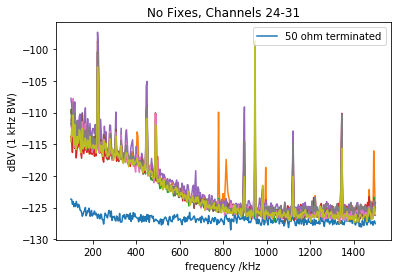
We can see many spurs throughout the scan. It is worth noting that many spurs are only visible in some channels and their respective intensity varies between channels.
Fastino Fixes
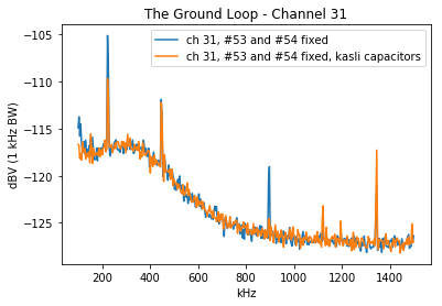
Issues #53 and #54 are addressed as discussed in the issue threads. This removes some of the spurs. Looking at channel 31 the effects are demonstrated.
Kasli Noise --- With Common Mode Chokes
(Edit: The below was measured with a Kasli v1.1. Newer versions of Kasli have an updated layout that may improve the situation.)
The switch mode supply on Kasli (Kasli IC6) operates at ~450 kHz. The supply generates many harmonics and sub harmonics at half the harmonic intervals. This noise is filtered on Kasli (for example there is a big drop-off across L6). However, the noise still couples to all rails across Kasli. In particular the switch-mode noise couples strongly to the Kasli P12V0 rail. Kasli is not a low noise design and the behavior may therefore be expected.
The coupling of the Kasli switch-mode noise to Fastino outputs is heavily grounding dependent and accounts for all remaining spurs within the frequency scan. The coupling of these spurs is Fastino output channel dependent. Below, channel 31 is shown as it was particularly sensitive.
Unlike the other switch-mode spurs on Kasli, the ~900 kHz 1st switch mode harmonic is larger on the Kasli side of FL1 than the PSU side. (Measurement relative to PSU ground, be sure to have no ground loop as it changes the measurement)
Adding 2.2 uF (X5R) capacitors on both sides of FL1 on Kalsi eliminates the ~900 kHz spur. (May be worth discussing for future Kasli revisions)
Using the TTi EL302RT floated power supply to power Kasli eliminates the spurs at 450 kHz and below. (See summary plot below)
Filtering the PSU power to Kasli suppresses the switch-mode harmonics above 1 MHz.
The power supply modifications above are summarised in this plot.
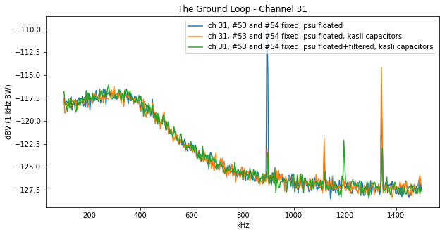
The 1.2 MHz spur is pickup from the environment.
Combining this with a ground strap between the Fastino front panel and the spectrum analyser ground, the following spectrum is observed for channel 31:
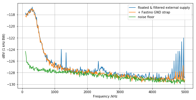
Note that this spectrum goes from 100 kHz to 5MHz. Previous spectra were from 100 kHz to 1.5 MHz.
Stuff That Didn't Help
Kasli Noise --- Without Common Mode Chokes
Spur free performance is achieved by using the Fastino fixes, a floated and filtered power-supply for Kasli and the capacitors on FL1 on Kasli.
Adding a ground connection from Kasli or Fastino ground to the analyser ground results in many spurs.
Spurs intensities are very dependent on relative positioning on components.
Spurs are not removed by cutting all digital lines and adding multiple filteres onto the P3V3MP and P12V0 supplies.
Summary
Edit: Fix plot axes
The text was updated successfully, but these errors were encountered: