- 材料 / Parts
- 組み立て手順
- 1. ダイオードをハンダ付けする / Solder diodes
- 2. スイッチ用PCBソケットをハンダ付けする / Solder PCB Hot-swappable sockets
- 3. ピンヘッダをハンダ付けする / Solder pin headers to PCB plate
- 4. ProMicroをハンダ付けする / Solder the ProMicro
- 5. リセットスイッチをハンダ付けする / Solder a reset switch
- 6. OLEDにピンヘッダをハンダ付けする / Solder a pin header to an OLED
- 7. OLEDをハンダ付けする / Solder the OLED to the the PCB plate
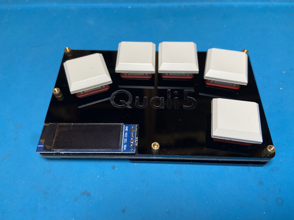
- 8. スイッチとキーキャップをトッププレートにはめる / Attach switchs and keycaps to the top plate
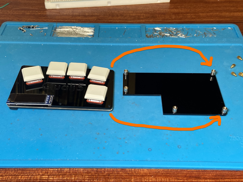
- 9. トッププレートをPCB基板にはめ込む / Mount the top plate over the PCB board
- 10. ボトムプレートにスペーサーをねじ止めする / Attach spacers to the bottom plate with screws
- 11. トッププレートとPCB基板をボトムプレートにはめ込む / Mount the top plate & PCB board over the bottom plate
- 12. トッププレートをねじ止めする / Screw the top plate and PCB board to bottom plate
- 13. ファームウェアを書き込む / Flash the Firmware
- 14. キーマップを変更する / Customizing keymap
| 名前 / Name | 個数 / Qty | 備考 / Remarks | 入手方法 / Where to buy |
|---|---|---|---|
| トッププレート Top plate |
1 | 注文方法 / How to Order | |
| PCB基板 PCB board |
1 | 注文方法 / How to Order | |
| ボトムプレート Bottom plate |
1 | 注文方法 / How to Order | |
| ProMicro | 1 | ピンヘッダ付属のもの Choose one includes pin headers |
https://shop.yushakobo.jp/products/pro-micro |
| OLED | 1 | ピンヘッダ付属のもの Choose one includes pin headers ピンソケットは不要です Pin Socket is not need |
https://shop.yushakobo.jp/products/oled |
| タクタイルスイッチ Tactile switch |
1 | リセットスイッチ用 Use as reset switch |
https://shop.yushakobo.jp/products/a0800ts-01-1 |
| キーキャップ Keycap |
5 | Kailh Chocロープロファイル互換のもの Choose Kailh Choc V1 compatible one |
https://shop.yushakobo.jp/products/pg1350cap-blank |
| キースイッチ Key switch |
5 | Kailh Chocロープロファイル互換のもの Choose Kailh Choc V1 compatible one |
https://shop.yushakobo.jp/products/pg1350 |
| スイッチ用PCBソケット PCB Hot-swappable sockets |
5 | Kailh Chocロープロファイル互換のもの Choose Kailh Choc V1 compatible one |
https://shop.yushakobo.jp/products/a01ps?variant=37665172553889 |
| 表面実装ダイオード Surface mount diode |
5 | https://shop.yushakobo.jp/products/a0800di-02-100 | |
| M2スリムヘッド小ネジ(5mm) Slim head small screw M2x5 |
5 | ボトムプレート用 Use to fix bottom plate |
https://shop.yushakobo.jp/products/a0800s2 |
| M2丸型スペーサー(6mm) Round Spacer M2x6 |
5 | https://shop.yushakobo.jp/products/a0800c2 | |
| M2ネジ(3mm) Screw M2x3 |
5 | トッププレート用 Use to fix top plate |
https://ja.aliexpress.com/item/33022872348.html |
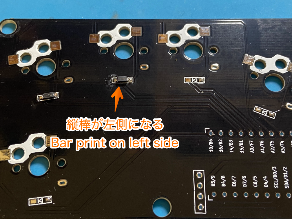
PCBソケットのマークがある面(あるいは、Quali5の名前が書いてない面)にダイオードをハンダ付けします。
その際、ダイオードの向きは、写真のように縦棒のマークが左側に来るように注意してください。
Solder diodes to the side which have PCB socket marks on it (or the side Quali5 is not printed).
Be careful to orient the diode so that the vertical bar mark is on the left side, as shown in the picture.
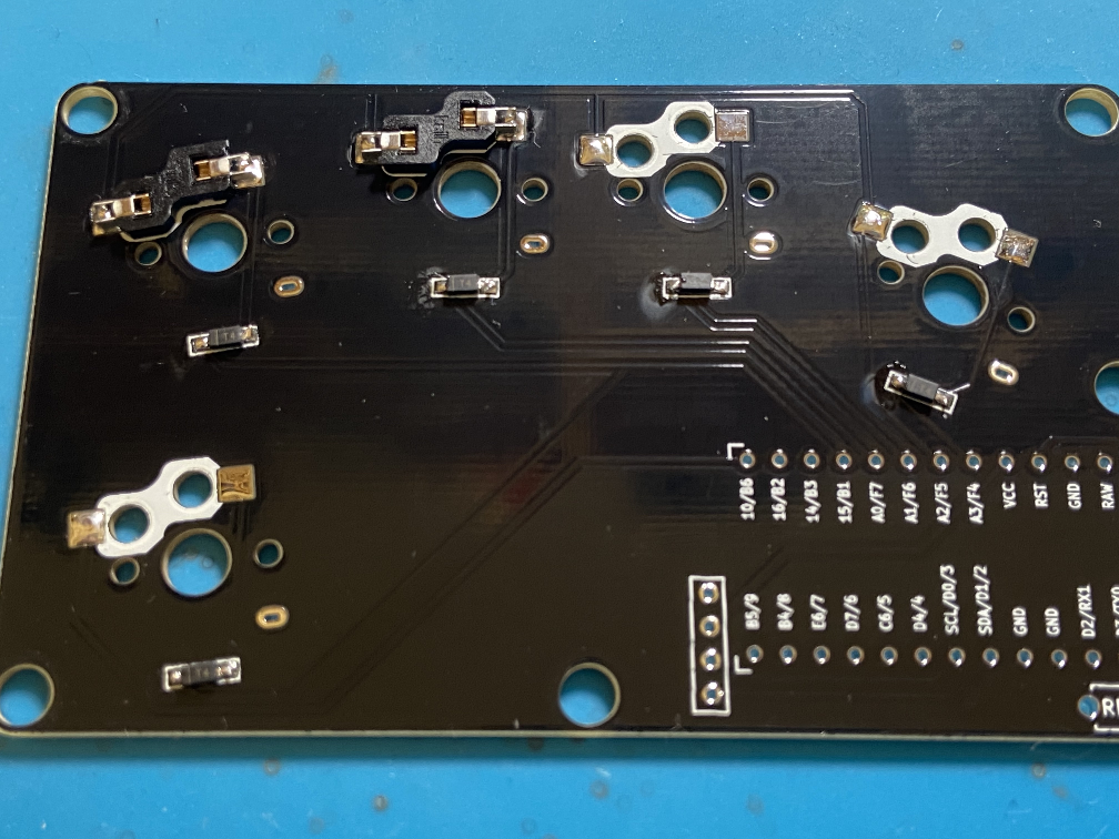
PCBソケットのマークに重なるように、スイッチ用PCBソケットをハンダ付けします。
Solder the PCB Hot-swappable sockets as the marks instructs.
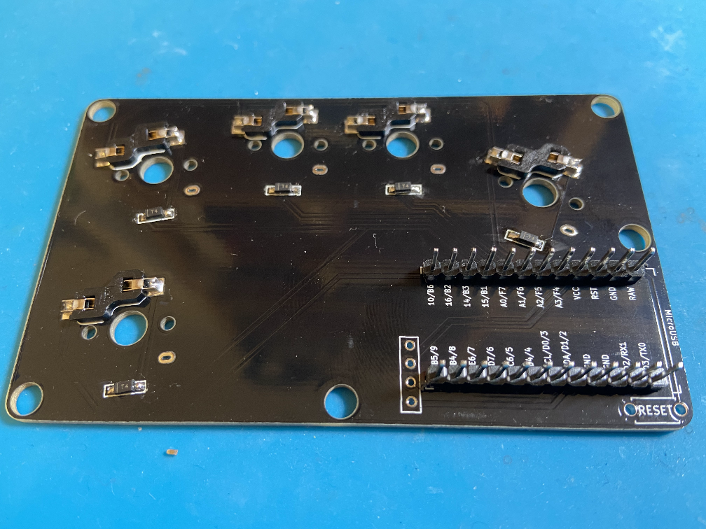
ピンヘッダをPCB基板にハンダ付けします。
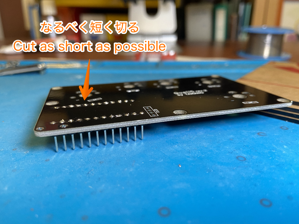
その後、2枚目の写真のように、裏側の余った足を切り落としてください。ここに出っ張りが残ると、後でトッププレートがPCBから浮いてしまう可能性があります。
Solder the pin headers to the PCB board.
Then cut off the excess legs on the back side, as shown in the second picture. If there is any protrusion left here, it may cause the top plate does not fit to the PCB board lately.
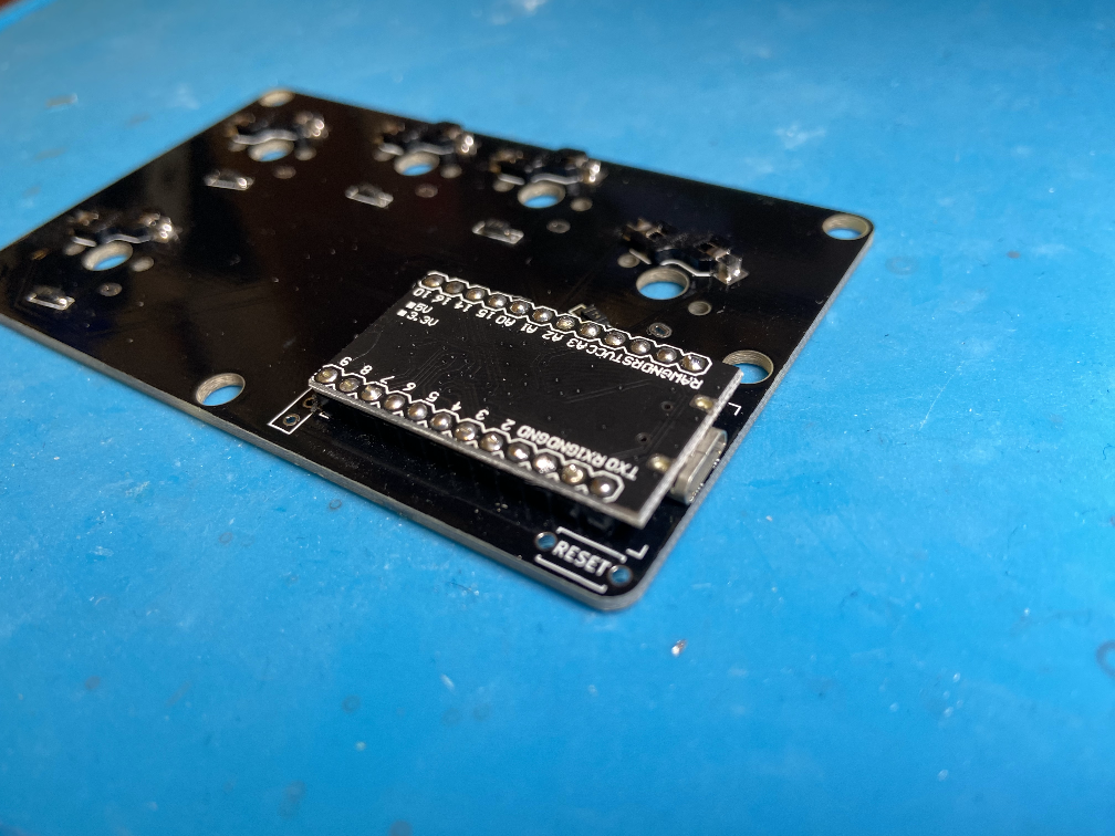
ProMicroをUSB差し込み口が外側になる向きで、PCB基板に半田付けします。
ここでも同様に、ハンダ付けの後で余った足を切り落としてください。
Solder the ProMicro to the PCB board with the USB port facing outward.
After soldering, cut off the excess legs as we did with pin headers.
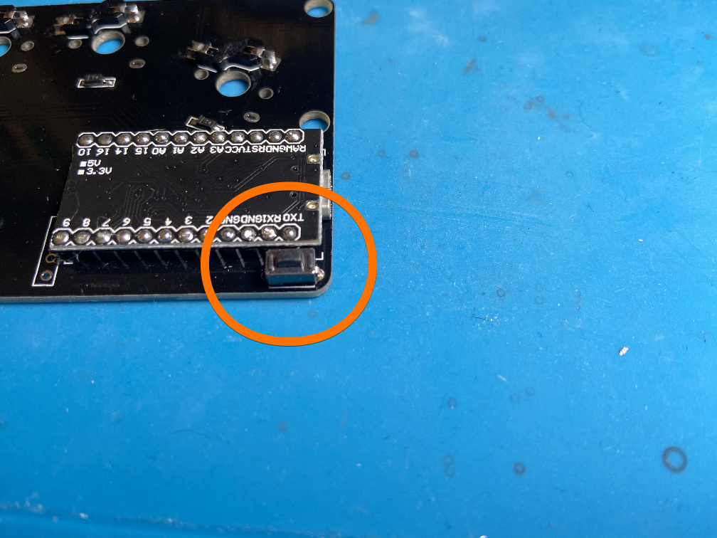
リセットスイッチをPCB基板にハンダ付けします。
Solder a reset switch to the PCB board.
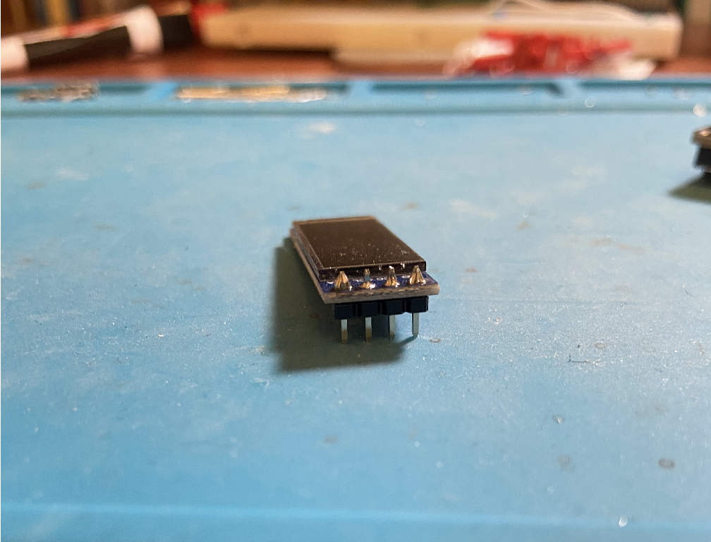
OLEDをPCB基板にハンダ付けする準備として、まずはOLEDに付属のピンヘッダをハンダ付けします。
この時、ピンヘッダの向きに注意してください。ピンヘッダは写真のようにディスプレイと反対側から差し込んだ上で、ディスプレイ側の面をハンダ付けします。
Solder a pin header that come with OLED to it mountable on PCB board.
Be careful to the direction of the pin header. Confirm that insert it from the opposite side of the display and then solder the display side as shown in the picture.
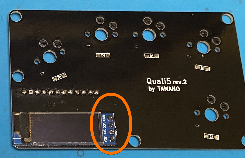
OLEDをPCB基板にハンダ付けします。
Solder the OLED to the PCB board.
キーキャップをキースイッチにはめた上で、キースイッチをトッププレートにははめます。
この時点では少しぐらつきますが、心配ありません。
Put the keycaps on the key switchs, and then put them on the top plate.
It may wobble a little at this point, but don't worry.
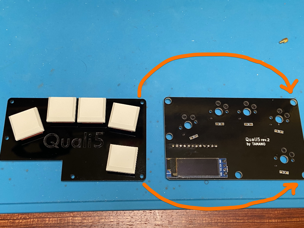
トッププレートのキースイッチの足がPCB基板のソケットの位置と合っている事を確認しながら、トッププレートをPCB基板にはめます。
はめるとスイッチがトッププレートから浮きますが、足の位置が合っていれば、上から抑えるとパチンとはまるはずです。
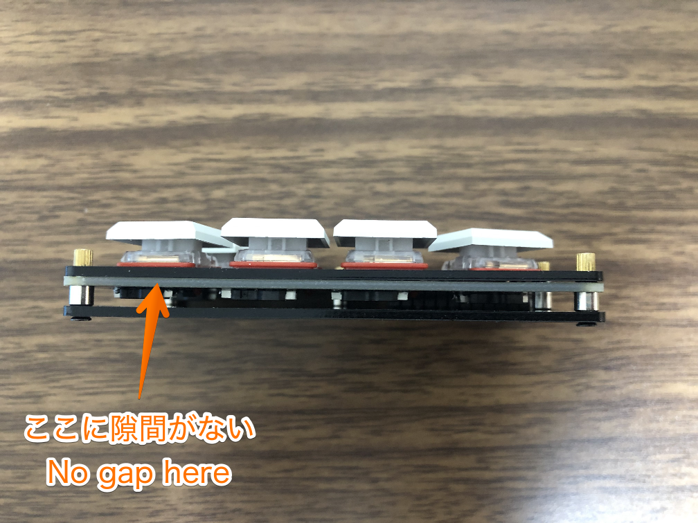
この時、2枚目の写真のように、トッププレートとPCB基板の間に隙間がない事を確認してください。もし、隙間ができてしまっている場合は、手順3に戻って、足をきっちり切ってください。
Fit the top plate to the PCB board, making sure that the legs of the key switchs on the top plate are aligned with the sockets on the board.
The switch will lift off the top plate when you insert it, but if the legs are aligned, it should snap into place when you push it in.
After that, make sure that there is no gap between the top plate and the PCB board as shown in the second picture. If there is a gap, please go back to step 3 and cut the legs off tightly.
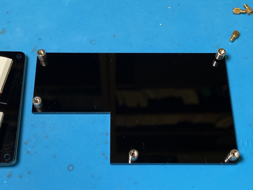
写真の向きにスペーサーをボトムプレートに取り付け、裏側からネジで固定します。
Attach the spacers to the bottom plate in the orientation shown in the photo, and fix it with screws from the back side.
トッププレートとPCB基板を、PCB基板の穴がスペーサーにはまるようにボトムプレートに被せます。
Mount the top plate and PCB board over the bottom plate with the spacers fit into the holes in the PCB board.
トッププレートの上からねじ止めでボトムプレートを固定して完成です。
Fix the bottom plate by screwing it on top of the top plate and you are done.
完成したキーボードをUSBケーブルでPCに接続した上で、ファームウェアを書き込みます。
ファームウェアの書き込む方法には、Pro Micro Web UpdaterやQMK Toolboxといったツールを使う方法と、QMKコマンドで直接描き込む方法の2種類があるので、いずれかを実施してください。
以下、それぞれについて説明します。
Connect the completed keyboard to the PC with a USB cable, and write the firmware.
There are 2 ways to write firmware, using a tool such as Pro Micro Web Updater or QMK Toolbox, or directly using QMK commands.
Each way is explained below. So follow one of them.
Pro Micro Web UpdaterやQMK Toolboxを使う事で、簡単にファームウェアを書き込むことができます。
なお、その際のHexファイル(コンパイル済みファームウェア)は、こちらのファイルを利用してください。
Pro Micro Web Updaterの使い方は、遊舎工房の説明が丁寧でわかりやすいので参考にしてみてください。
By using Pro Micro Web Updater or QMK Toolbox, you can easily write the firmware.
Please use this file as the Hex file (compiled firmware).
以下のコマンドを実行してファームウェアを書き込みます。
まだQMKをインストールしていない場合は、こちらの手順に従って 2. ビルド環境を準備する まで実施して環境を整えた上で、以下のコマンドを実施してください)
Execute the following commands to write the firmware.
If you have not installed QMK yet, please follow this procedure to 2. Prepare Your Build Environment, and then execute the following command)
cd your_workspace_directory
qmk setup tamano/qmk_firmware --branch quali5
cd qmk_firmware
qmk flash -kb tamano/quali5 -km via # 画面で指示されたらリセットボタンを押す / Push the reset button when instructedファームウェアを書き込んだ後、キーマップを変更する方法についてはキーマップのカスタマイズ方法 / How to Change Key Mapsを参照してください。
For information about changing keymap after writing the firmware, please refer to How to Change Keymaps.