You will need to solder the "135" diode uniquely if using 3u bars, even if your diodes came pre-installed!
If your Xiao and Diodes came pre-installed, jump to the Modifications section.
When removing Hull or Campiander tabs on the FR4 plate, you must score the perforations with a sharp knife before snapping them off. Failure to score the perforations will result in the plate bending or breaking.
- PCB
- Plate
- Xiao BLE
- Diodes
Battery(not included in V2)(Asssembly alignment 3D printed parts)(not included in V2)
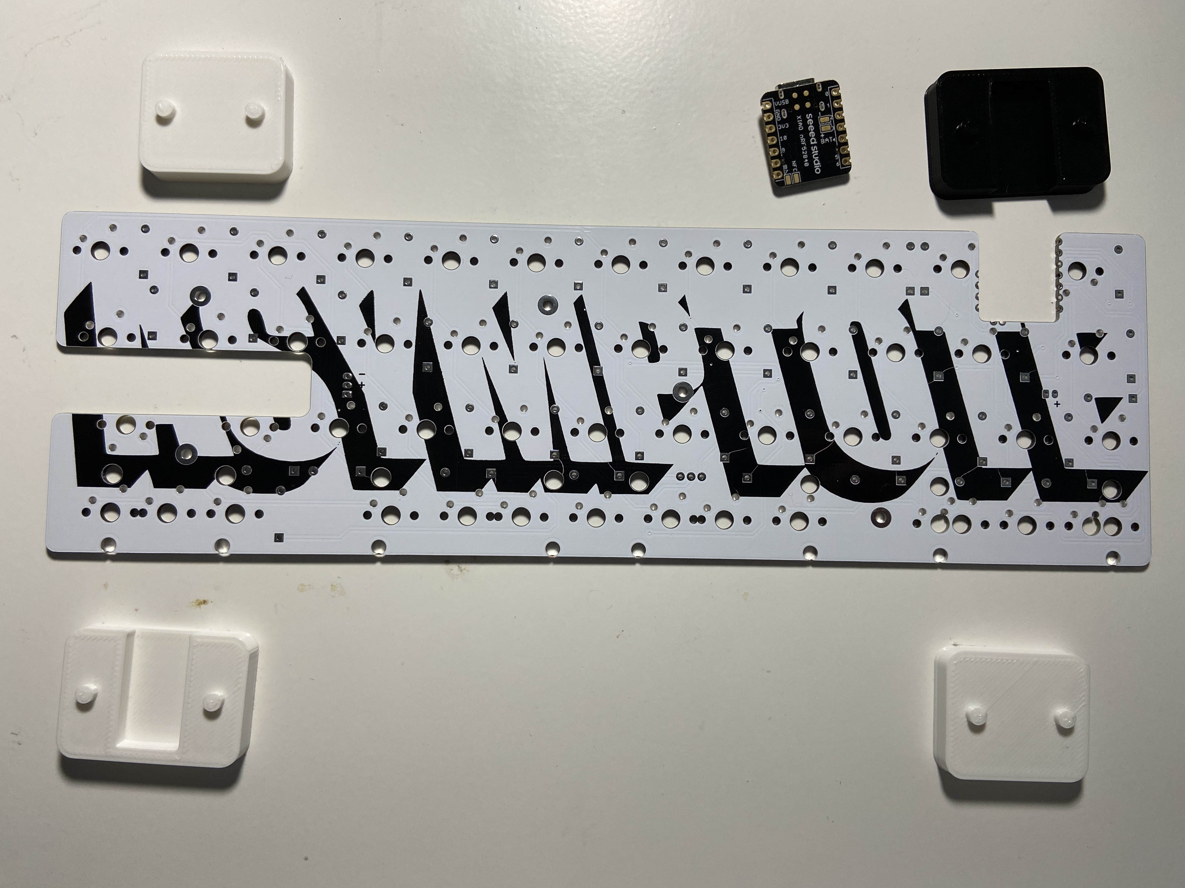
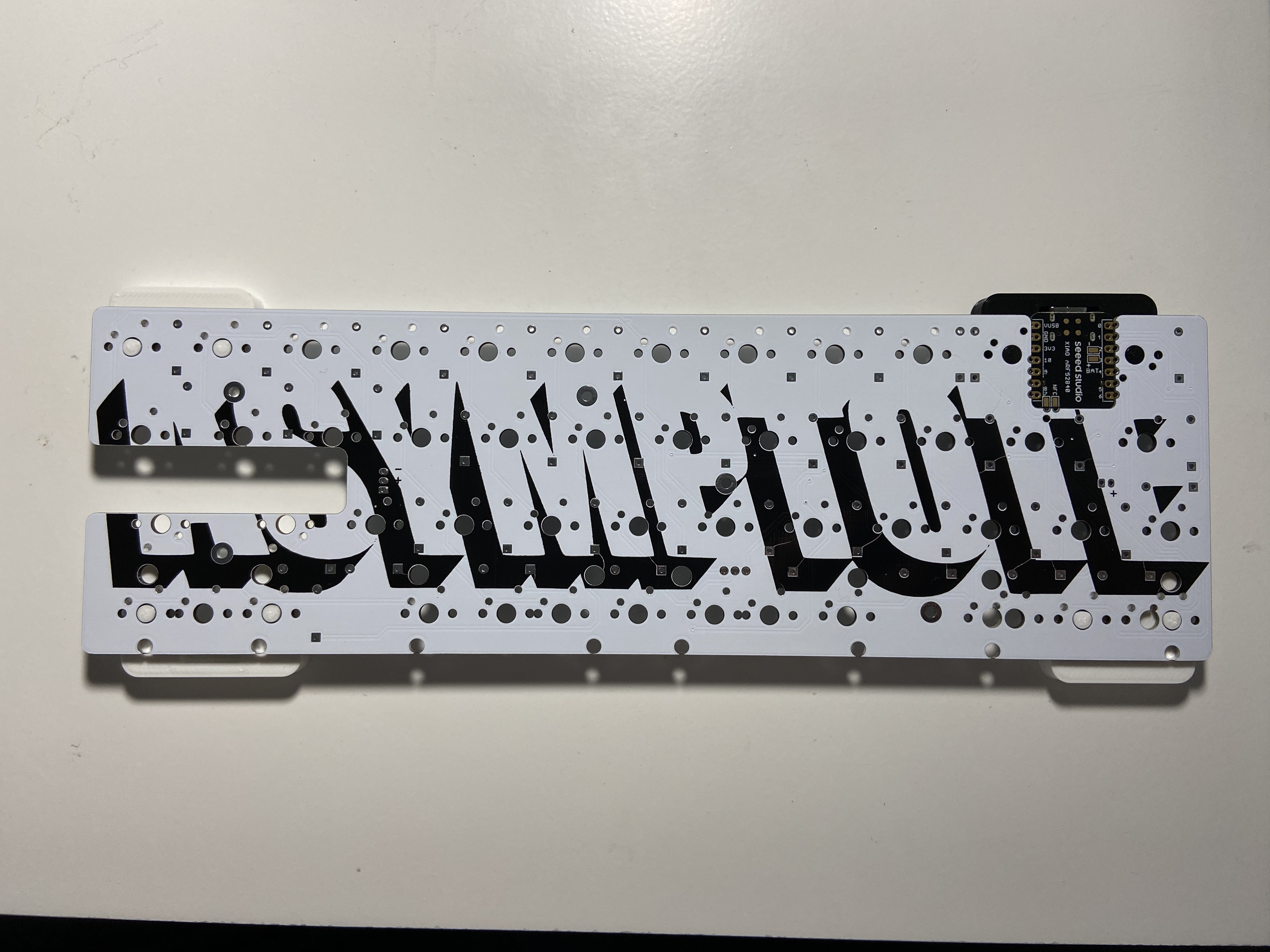
Using the included 3D printed parts, align the Xiao to the PCB.
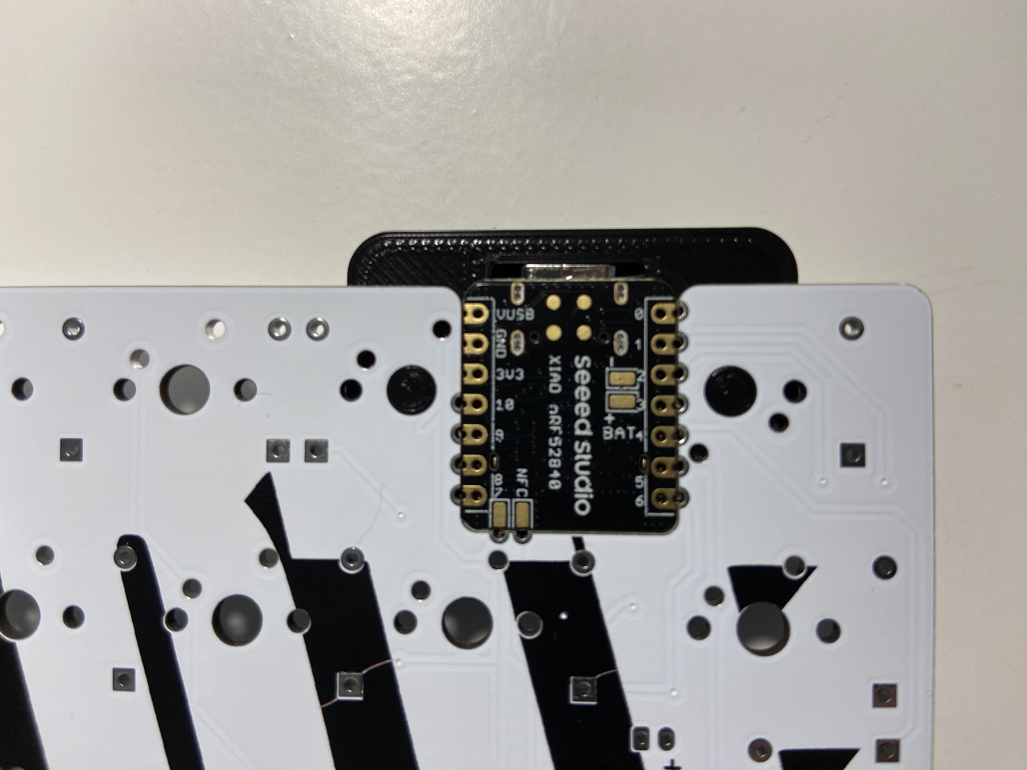
The USB port should be facing the bottom of the PCB, and be pressed up against the internal lip of the black alignment piece.
The other alignment pieces can be placed in the other corners to provide a level surface.
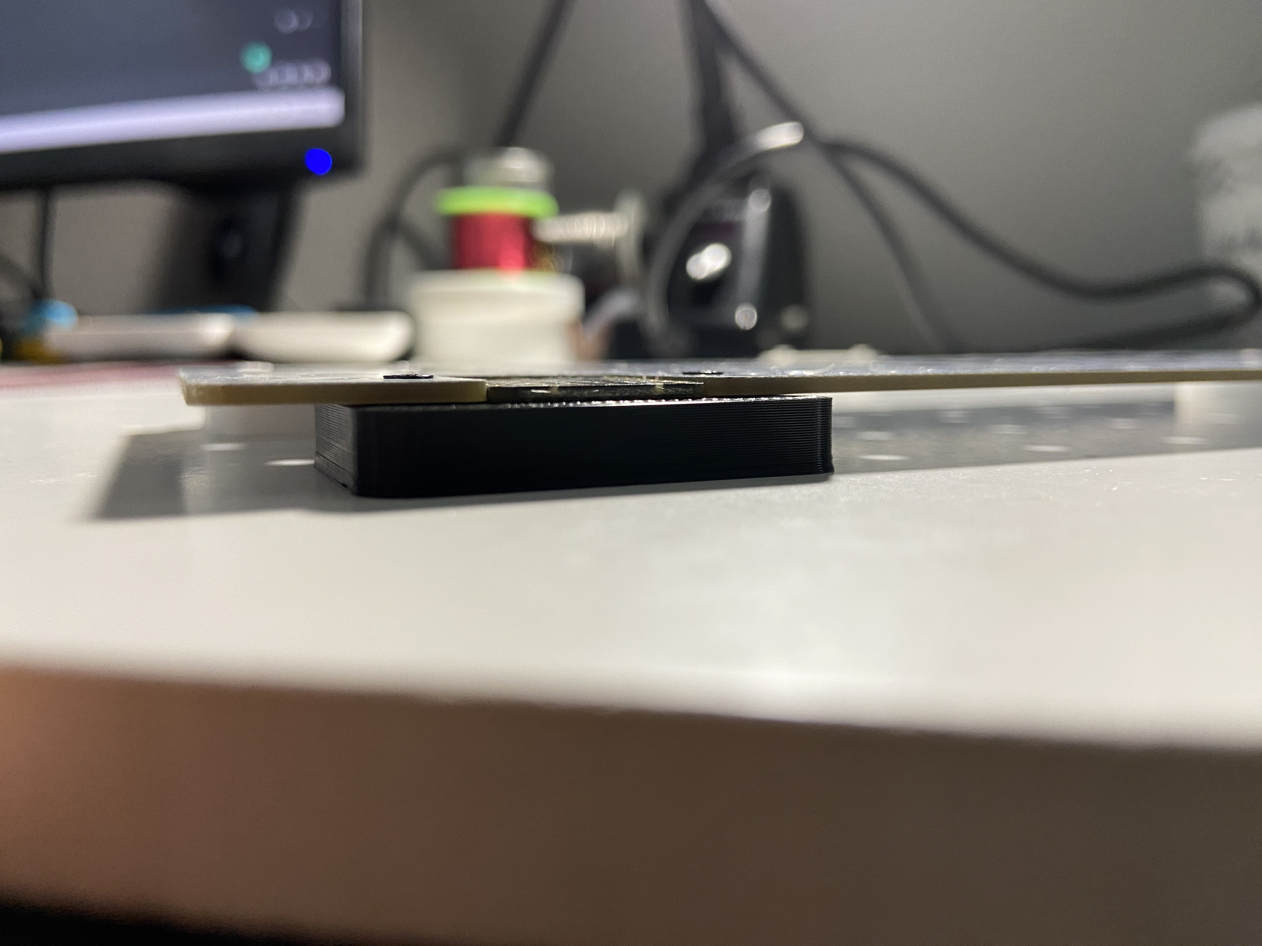
The Xiao sould sit flush to the bottom of the PCB. It is thinner than the PCB, so the top surface, facing you, will be a bit recessed down.
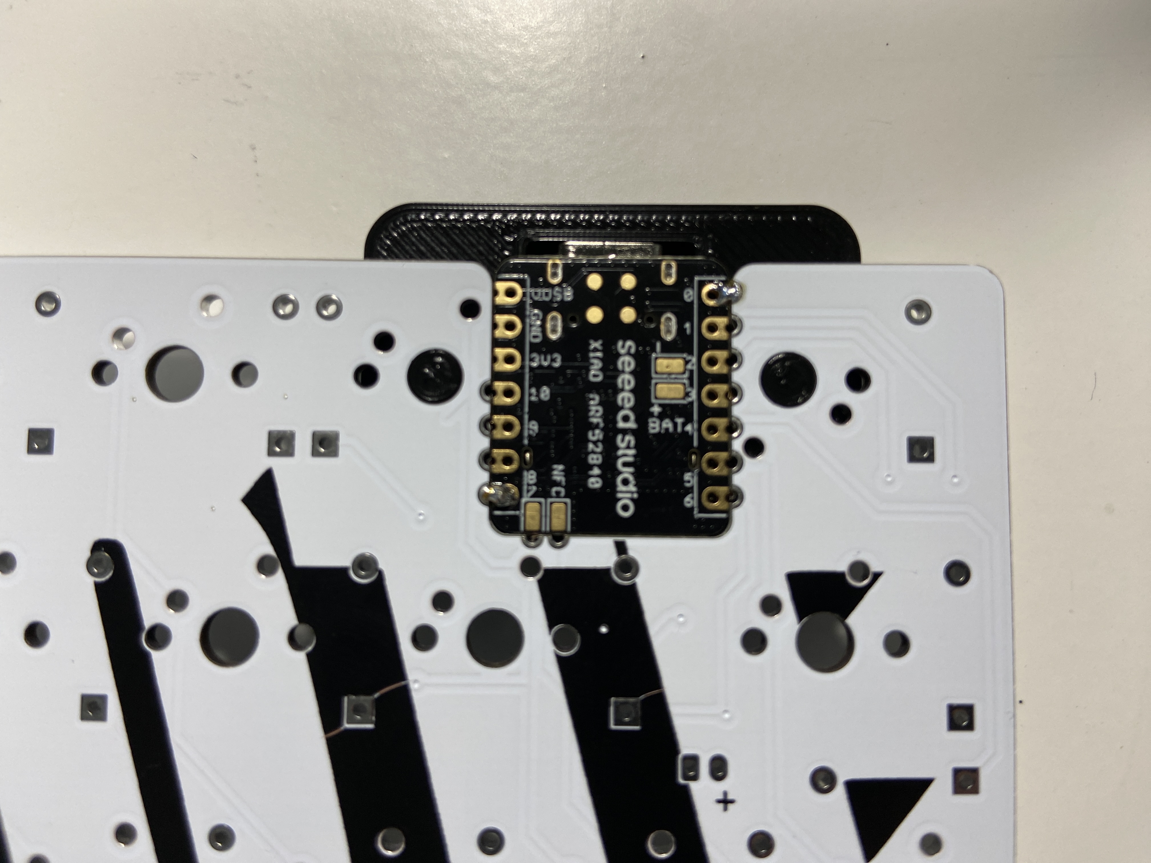

Tack opposite corners of the Xiao module in place with a bit of solder, and check the fitment of your Minivan Case. Make adjustments as needed by heating up the offending corner's solder.
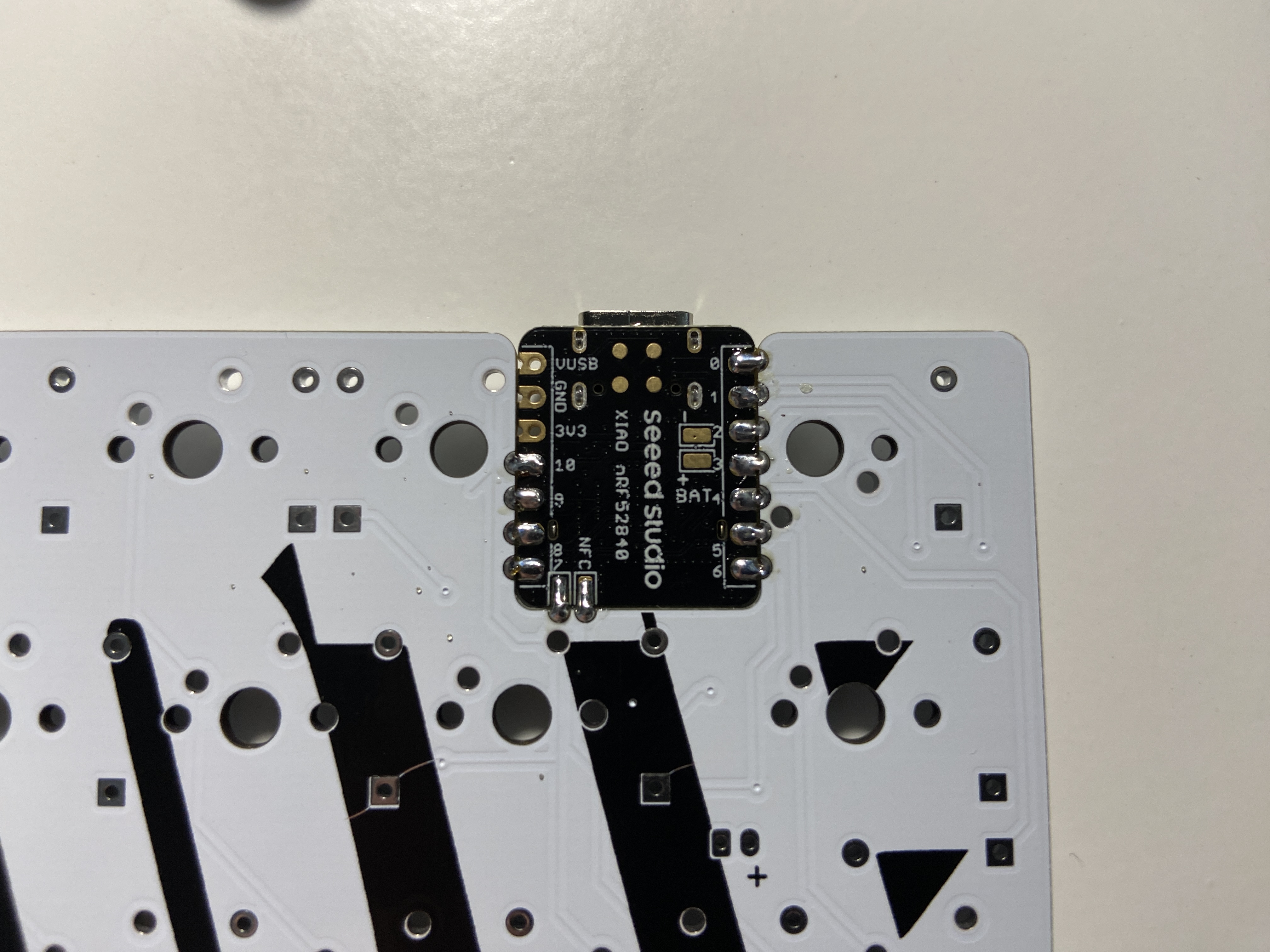
Remove the PCB from your case, and solder all pins on the top of the PCB.
Do Not Forget the NFC pins. These need to be soldered as well!
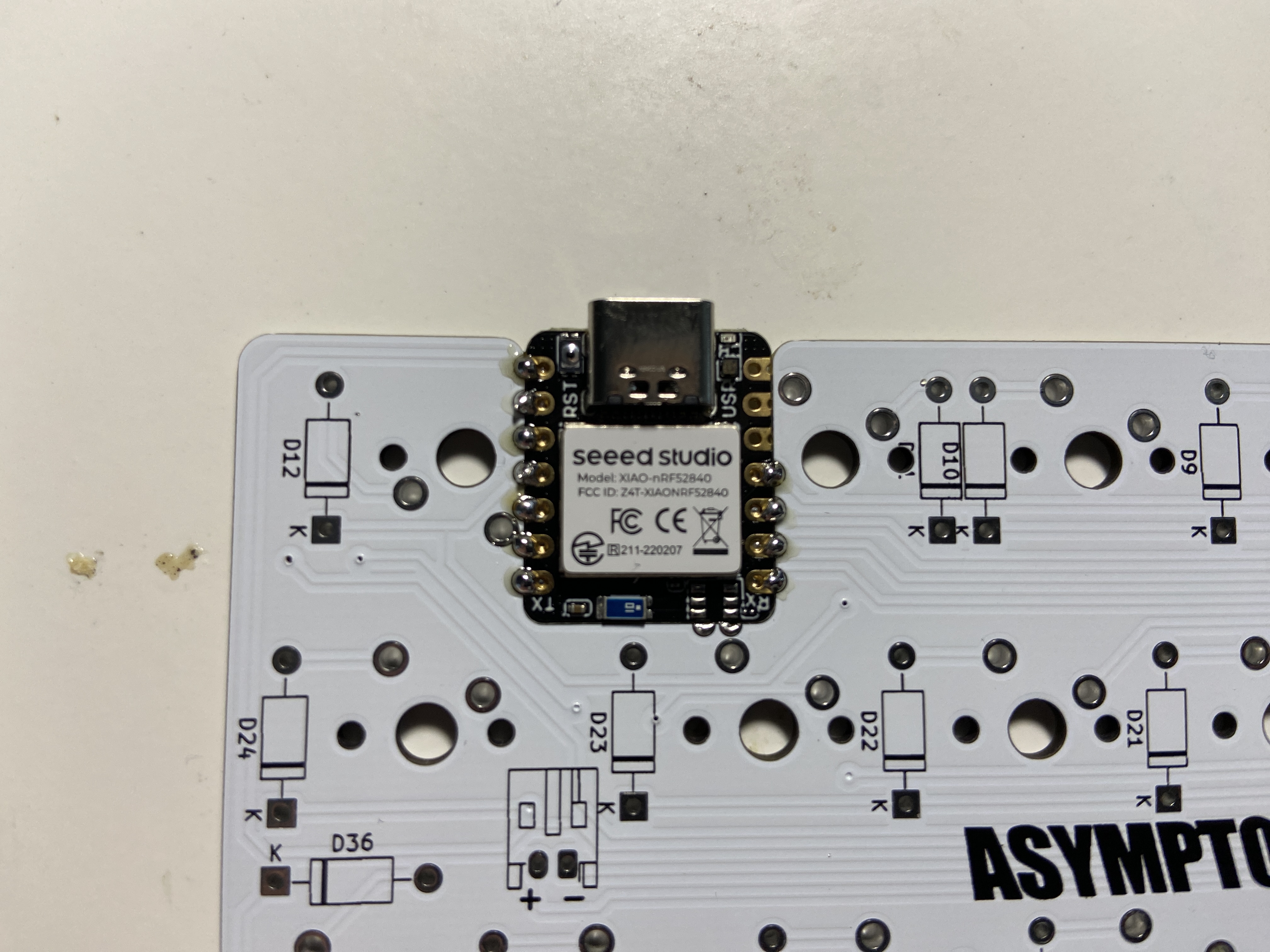
Then, flip the assembly over and solder the pads from the back.
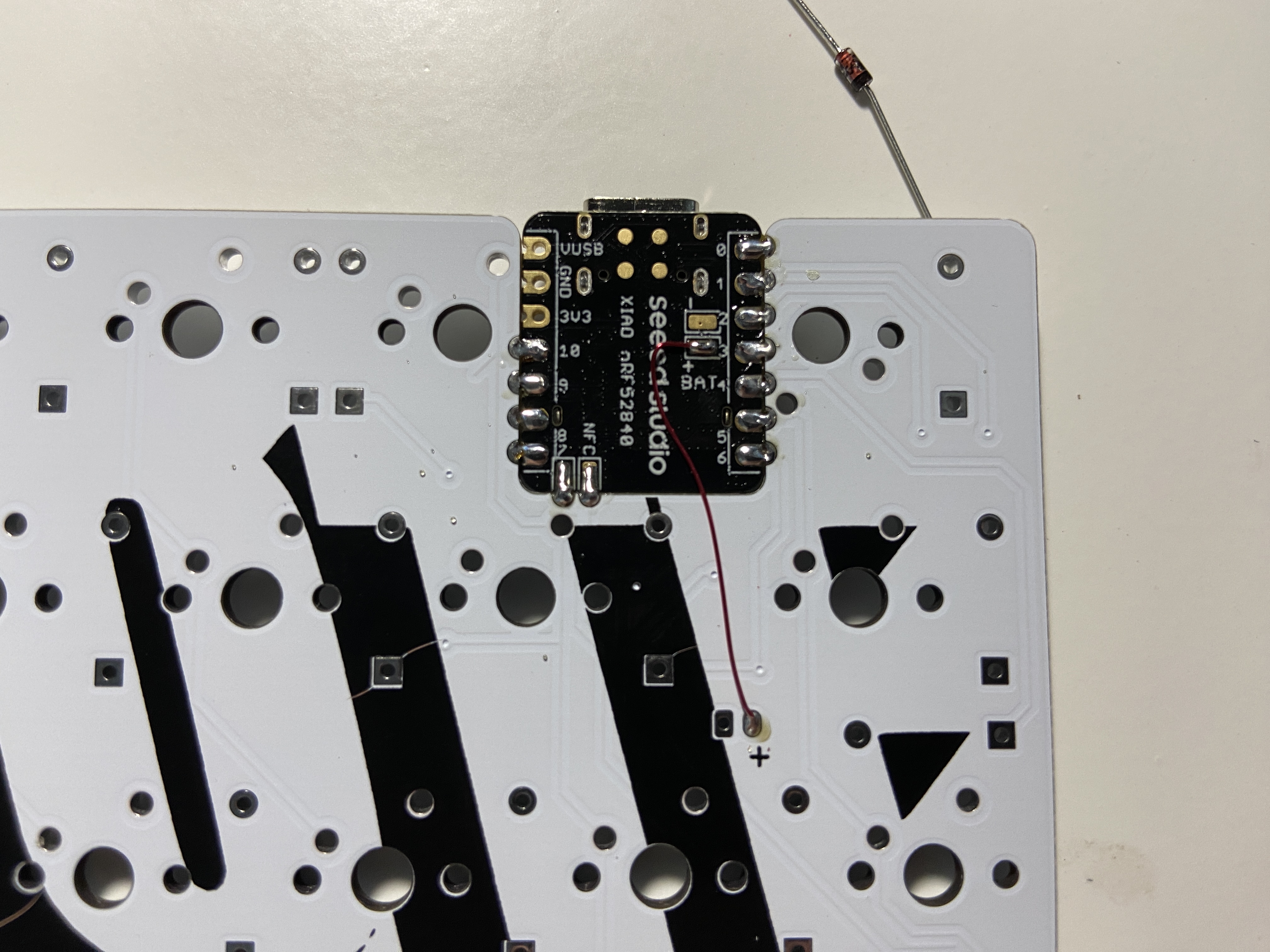
Solder a spare bit of wire as pictured, from the outer (+) battery pad by the Enter key, to the Batt+ pad on the Xiao
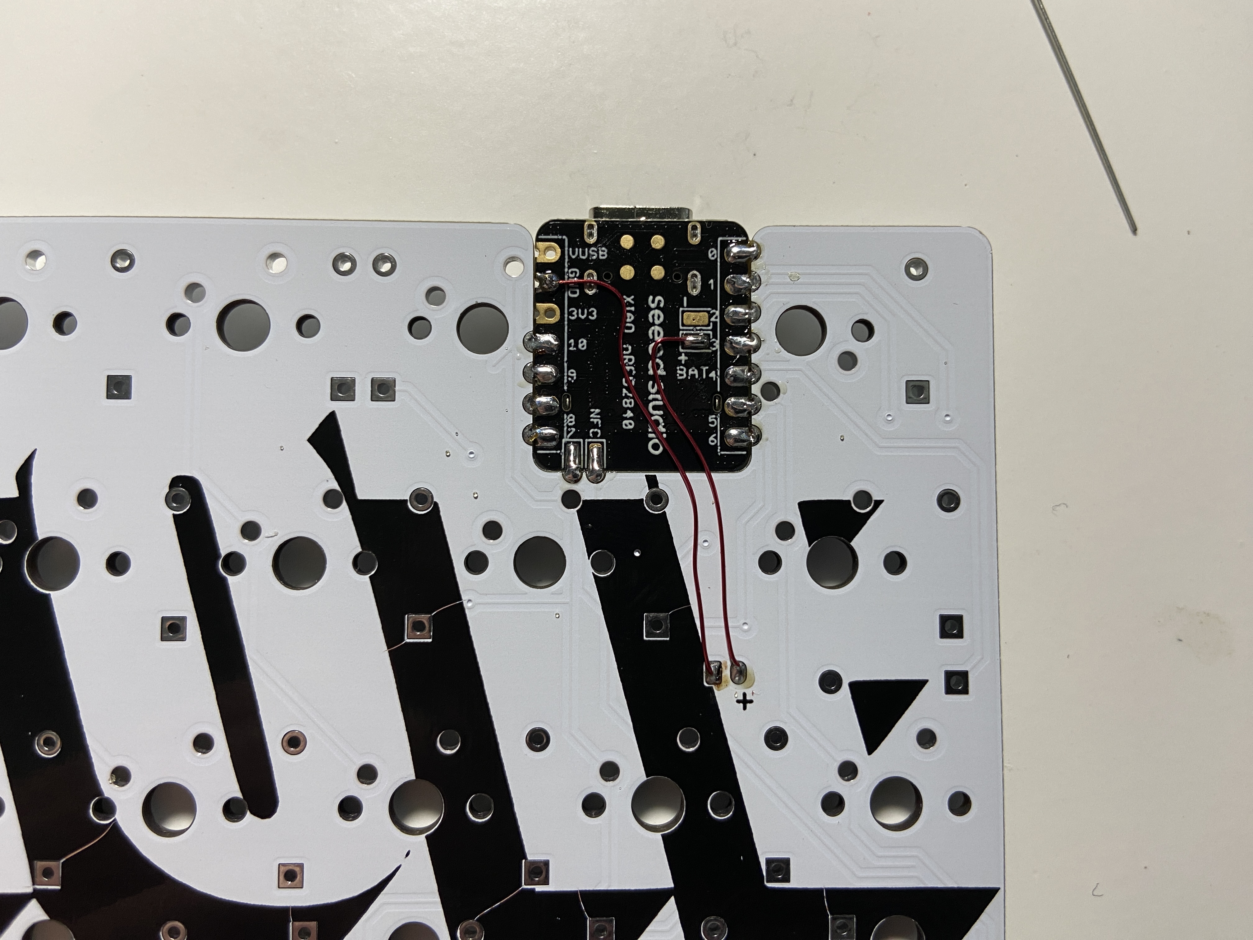
Solder another wire from the inner battery pad by the Enter key to the GND or Batt- pad on the Xiao.
I recommend the GND pad, since it is easy to short the two Batt pads.
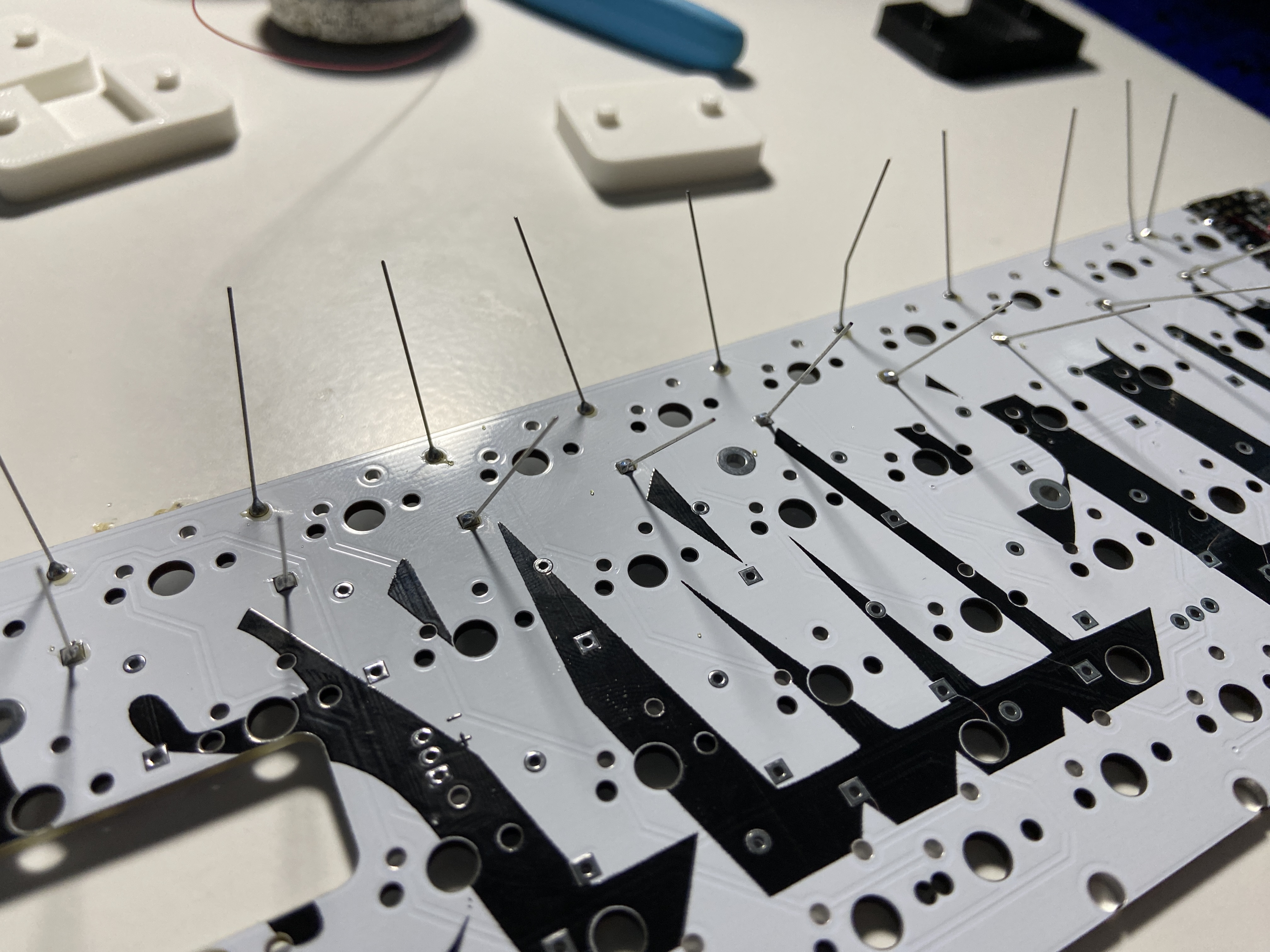
Stuff the PCB with diodes, all diodes are either pointing down or to the left (when viewed from the bottom)
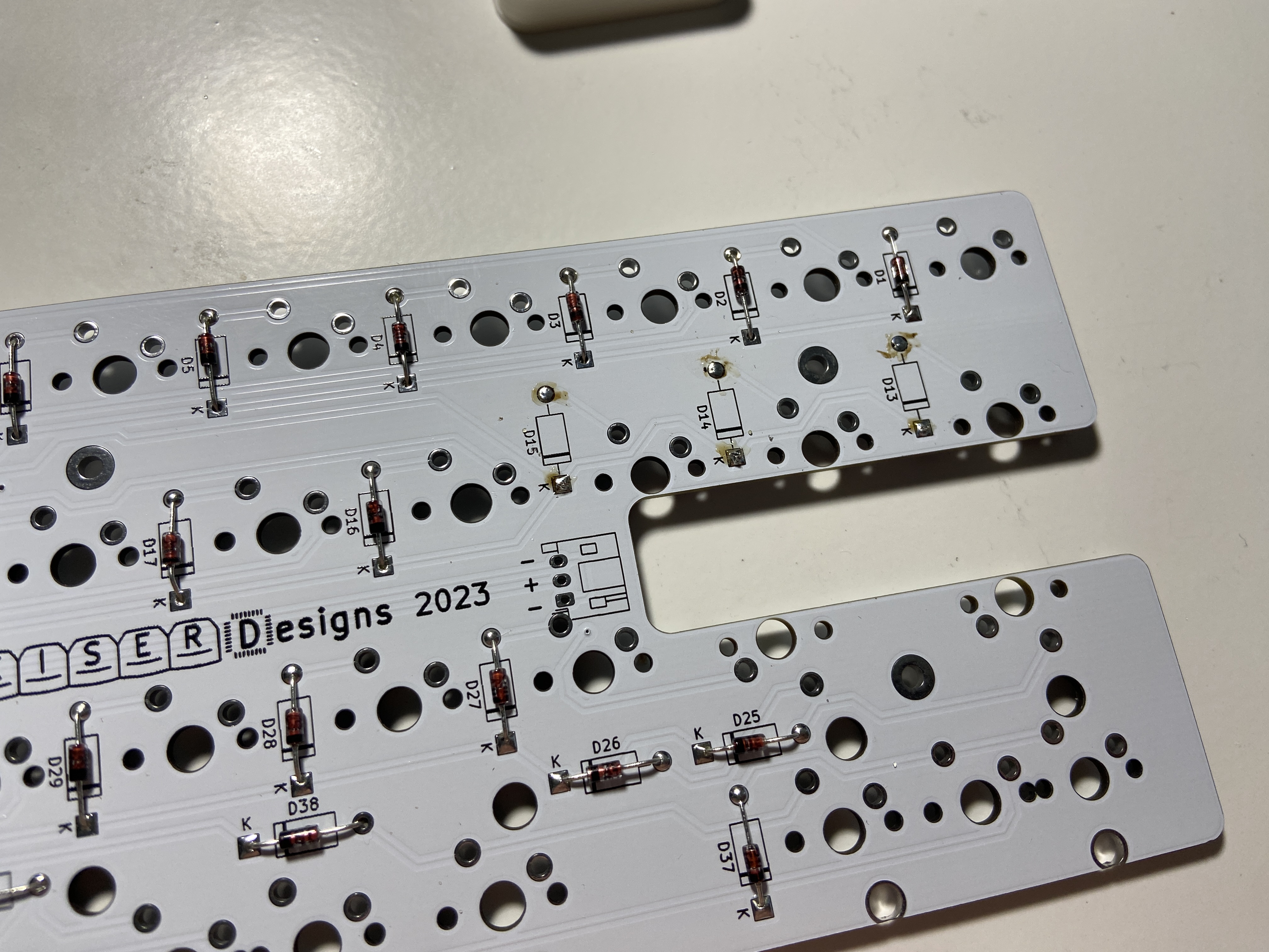
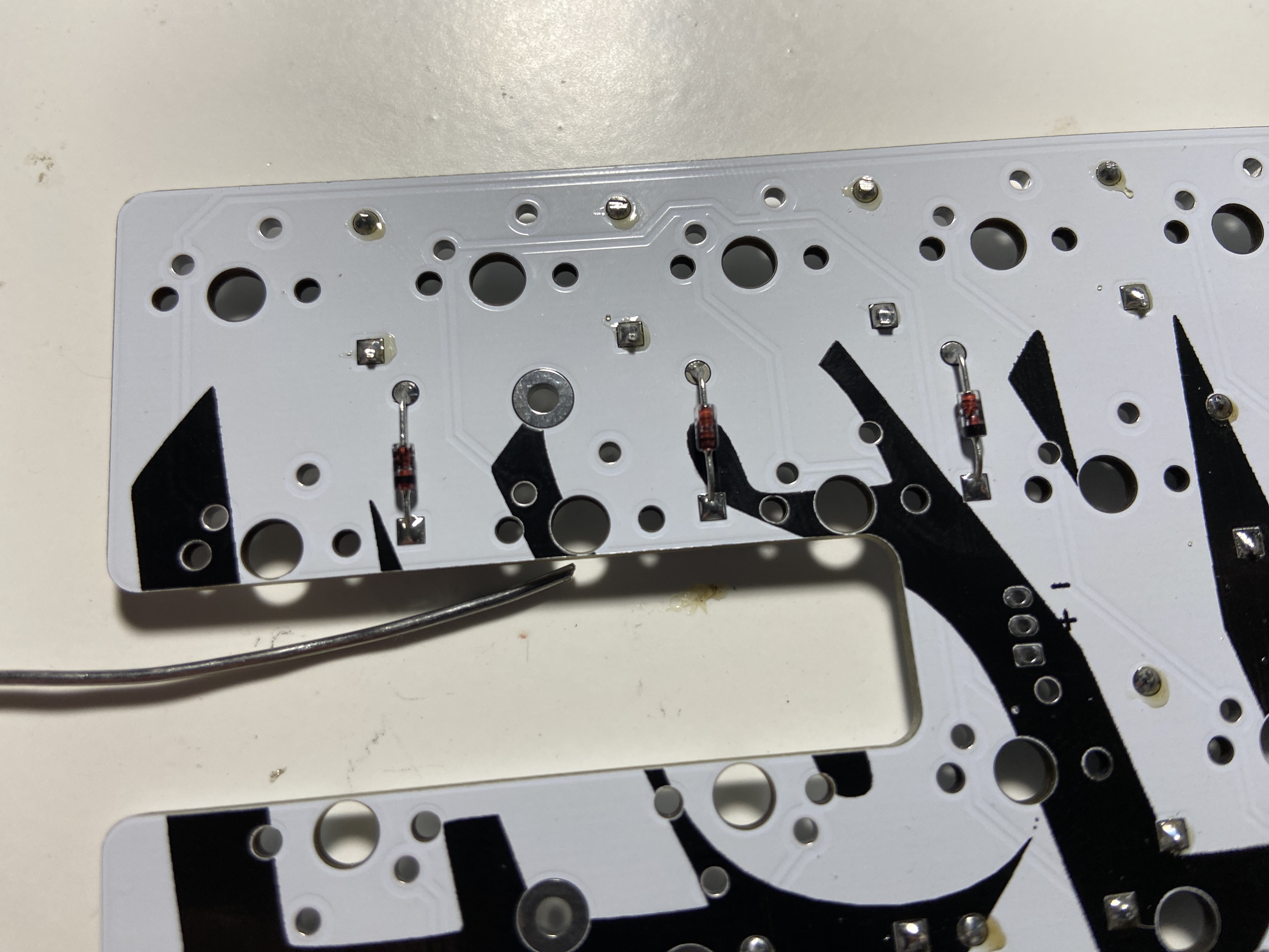
The three diodes directly over the battery cutout interfere with injection molded tray-mount cases, solder those on the top side and trim their legs very flush on the bottom.
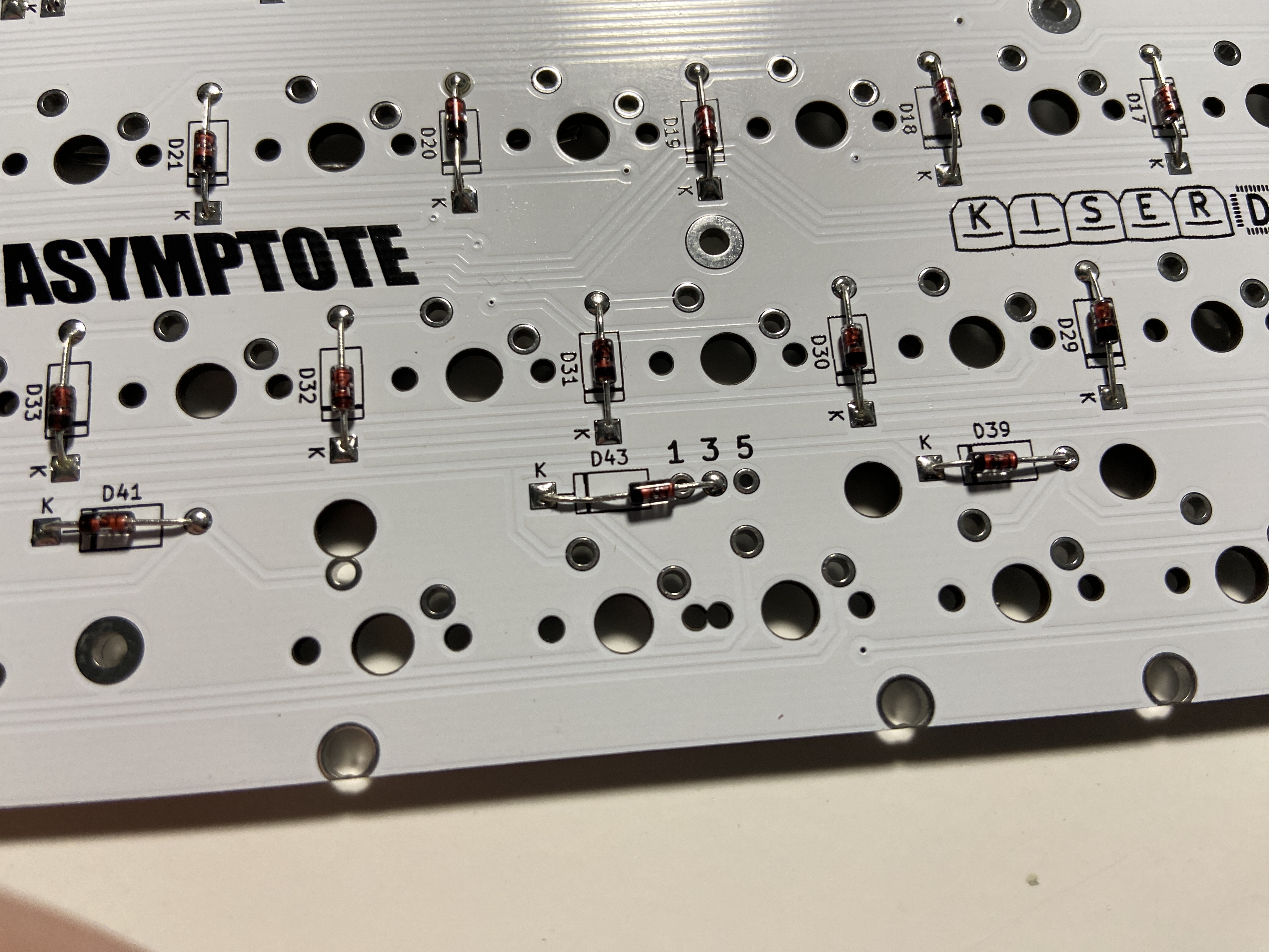
The diode with the "135" markings is special.
If you are using a 3u spacebar layout, this diode needs to be soldered to a certain pad, 1, 3 or 5, depending on your overall bottom layout.
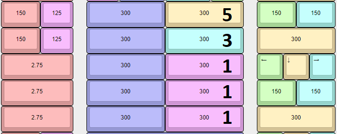
Given your desired layout, solder this diode on the corresponding pin as pictured.
Switches that are colored the same in this screenshot are electrically wired together. You are limited to 6 keys on the bottom row, no matter what layout you choose.
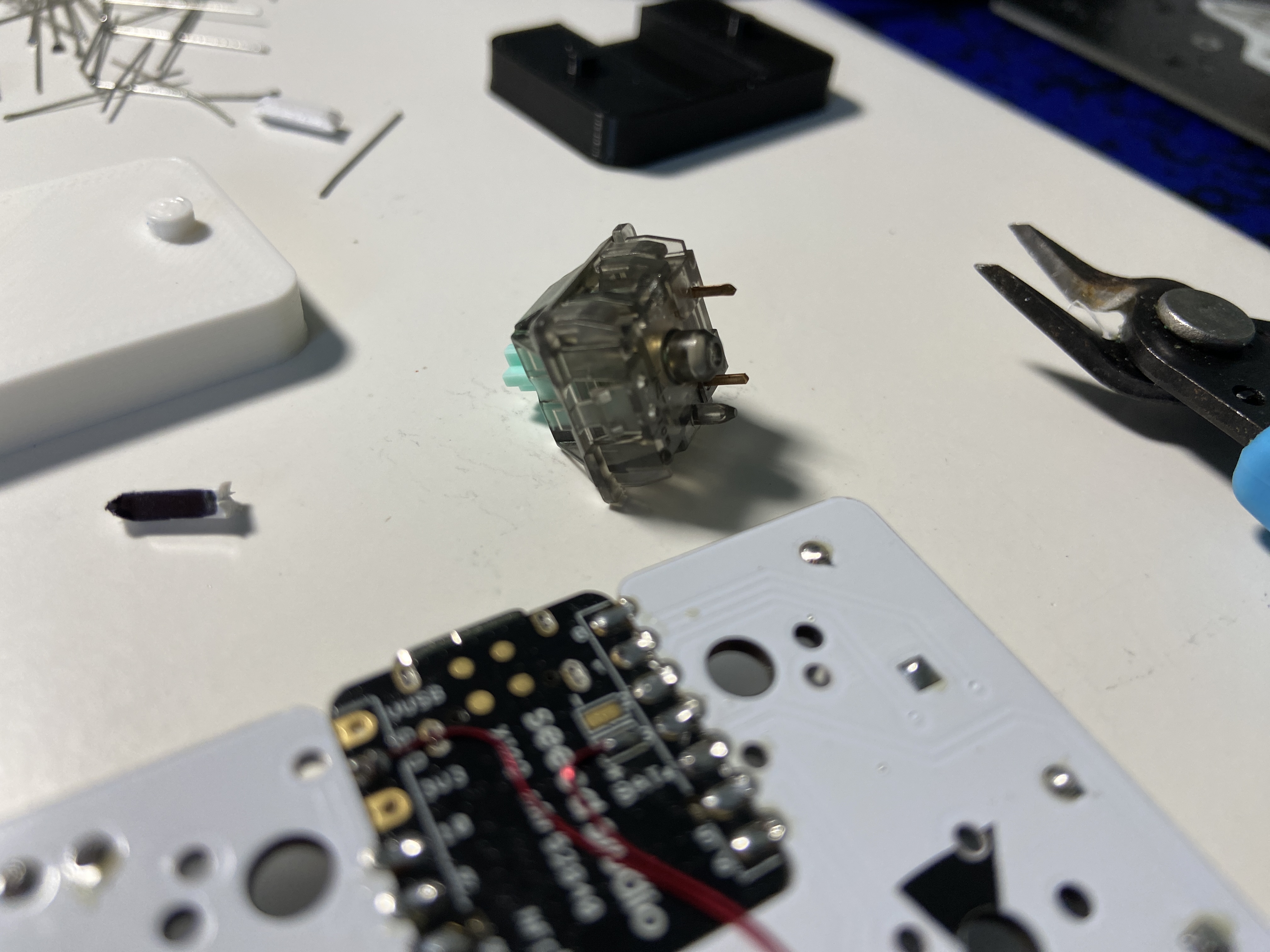
Because the Xiao module is between the two upper-right switches, when using 5-pin switches, the inside 5th pin of those two switches needs to be removed.
Cut them with a pair of flush cutters:
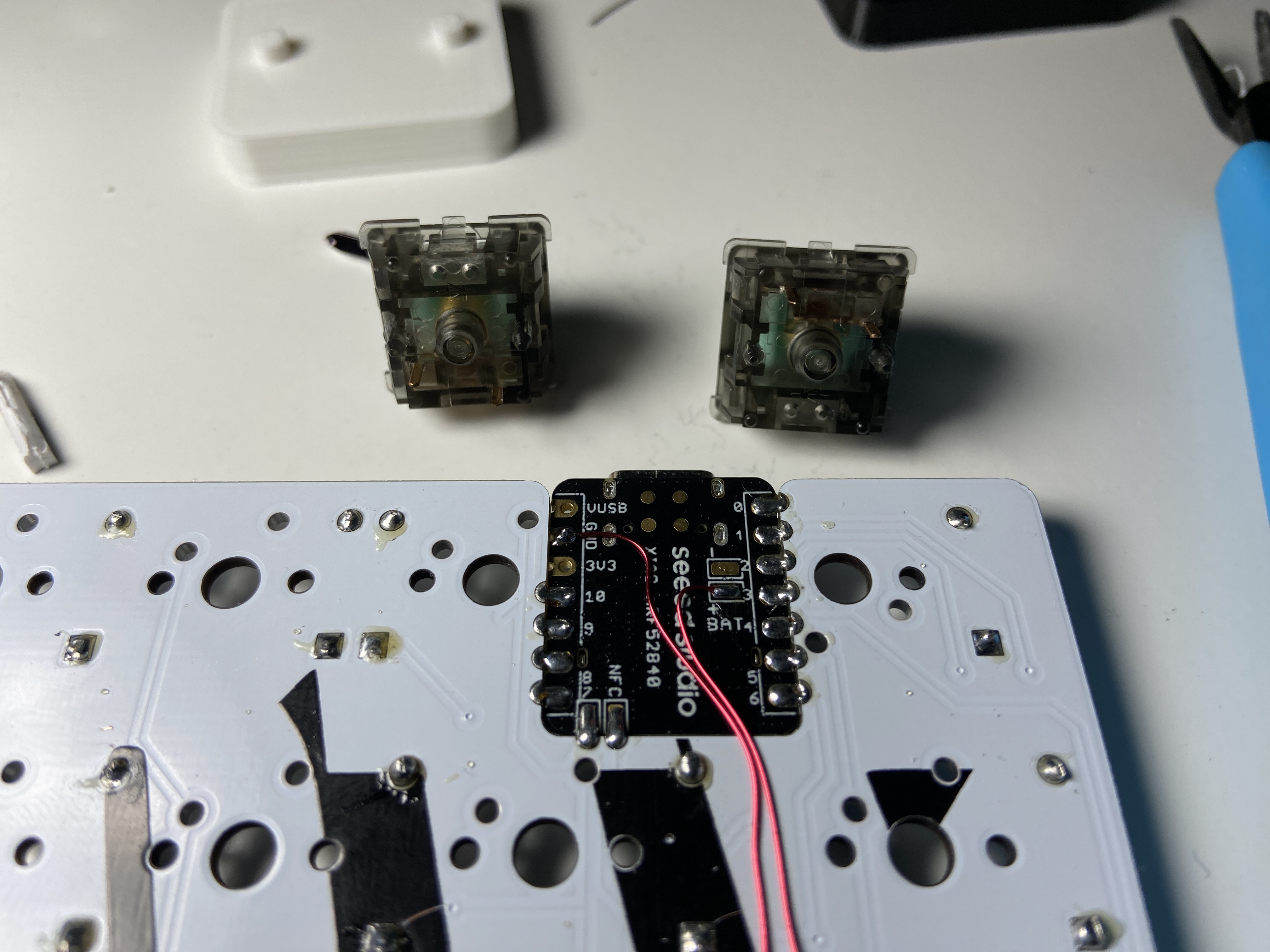
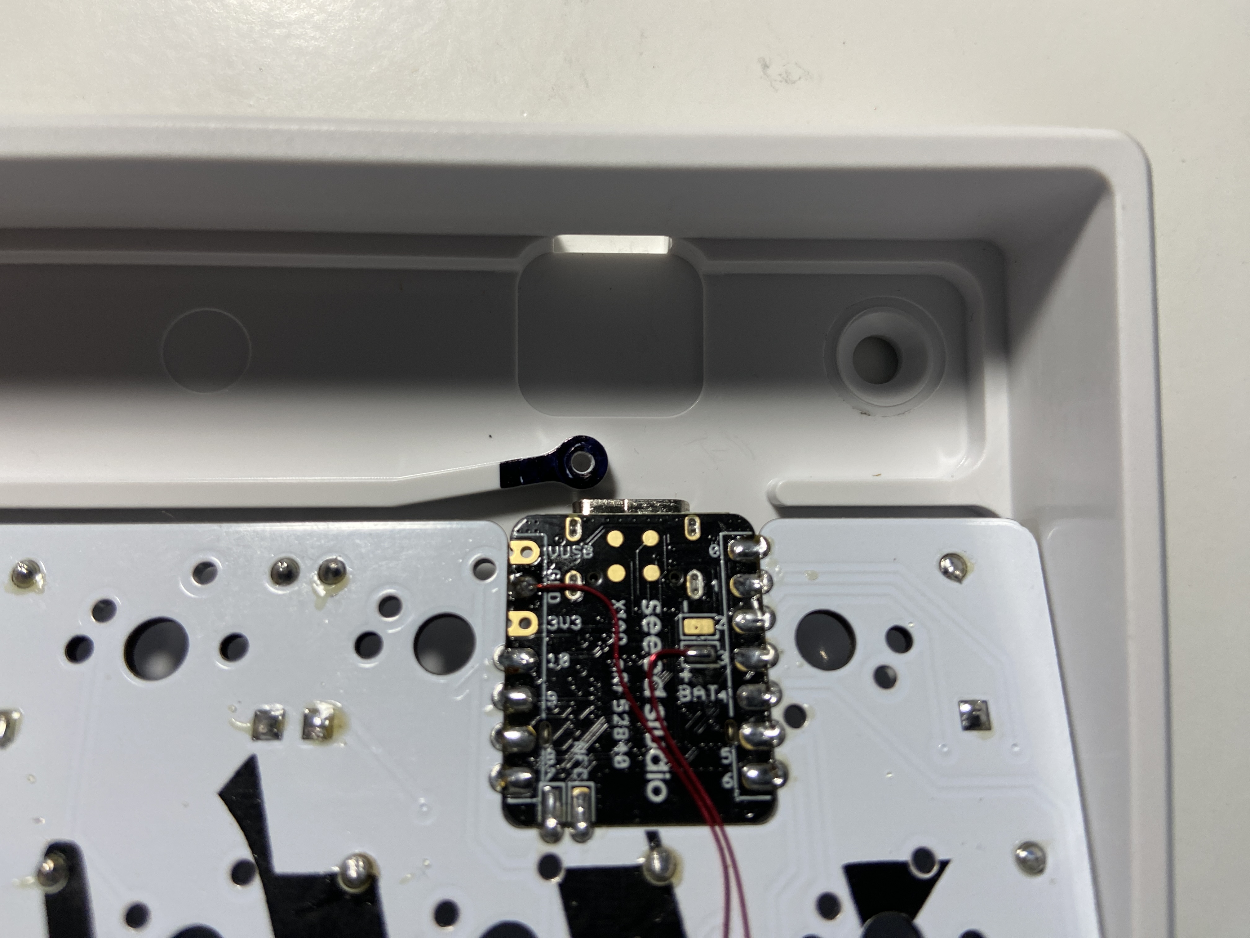
The Xiao and Battery interfere with some tray-mount cases, which will need to be modified.
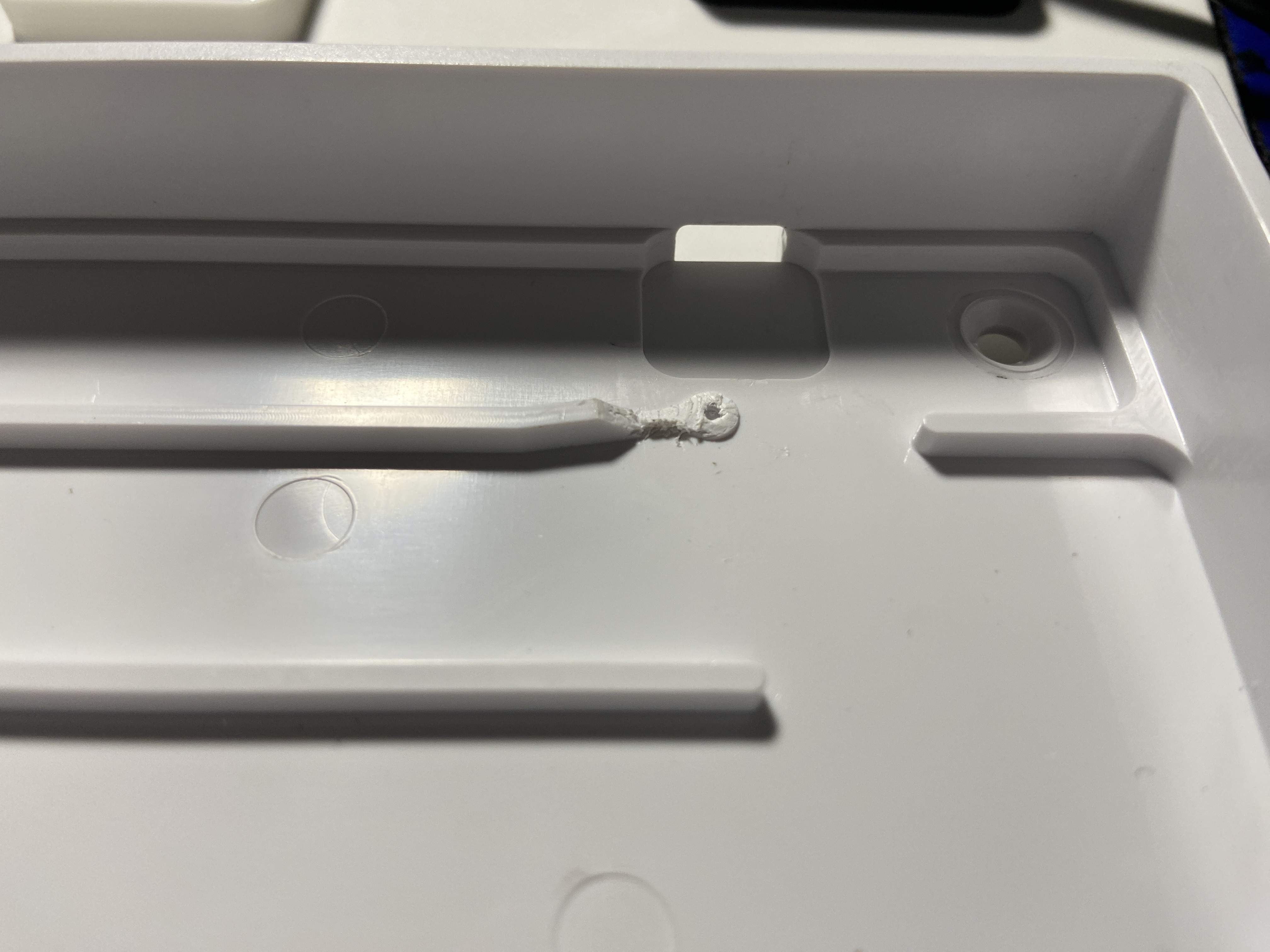
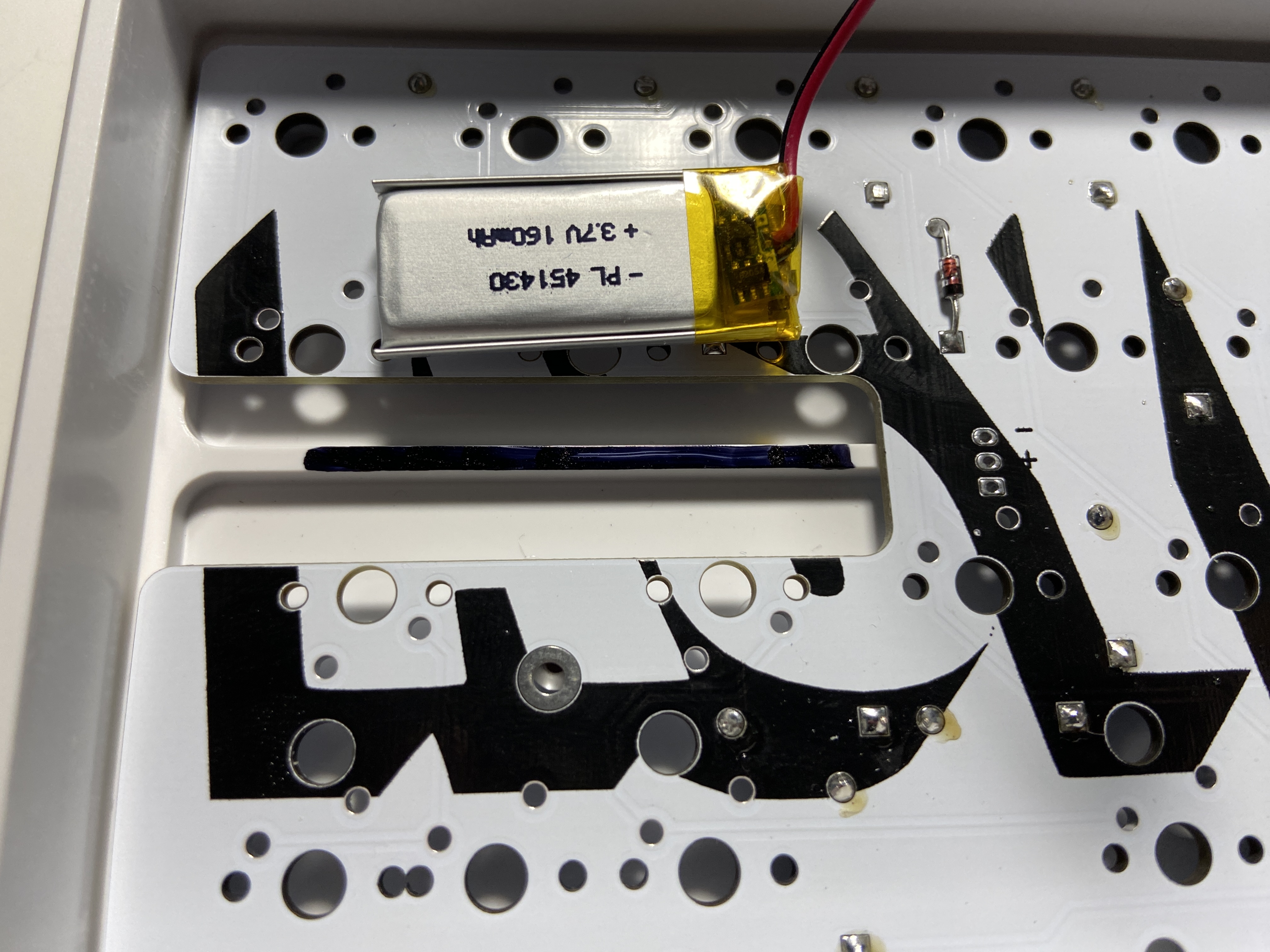
And likewise for the battery:
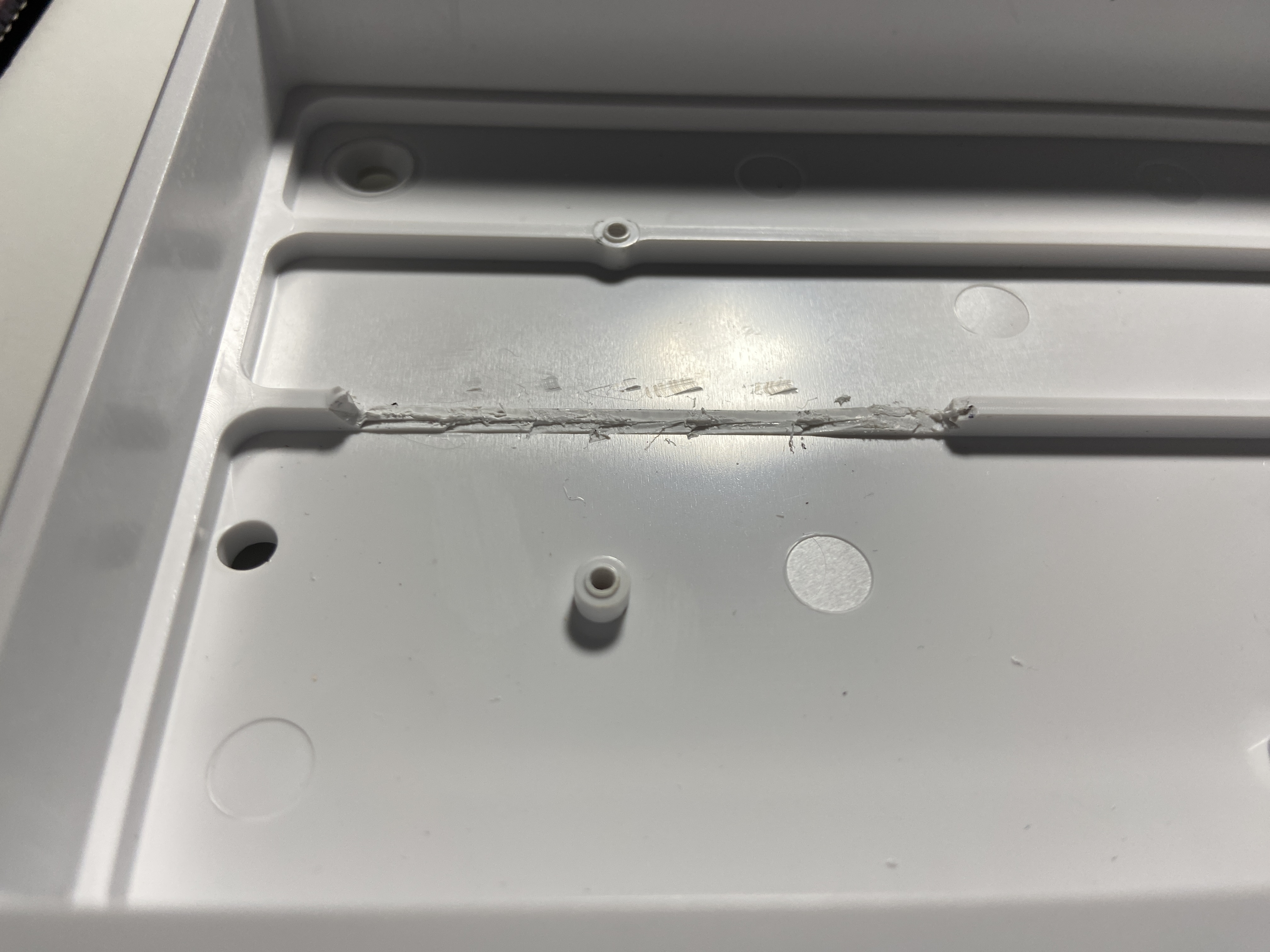
Depending on the your bottom row layout, you may need to remove the bottom-most left standoff, under the left side of the spacebar area:
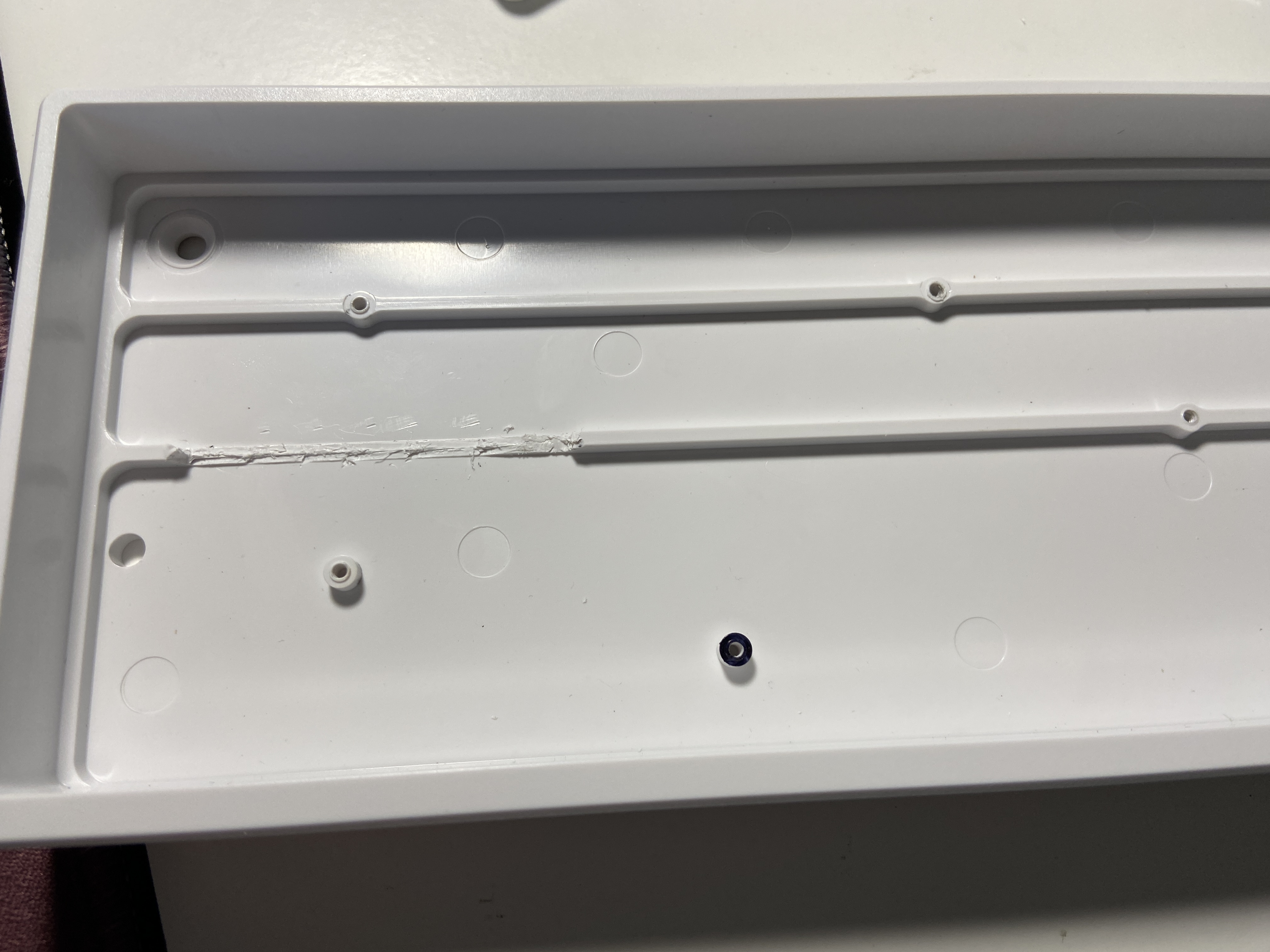
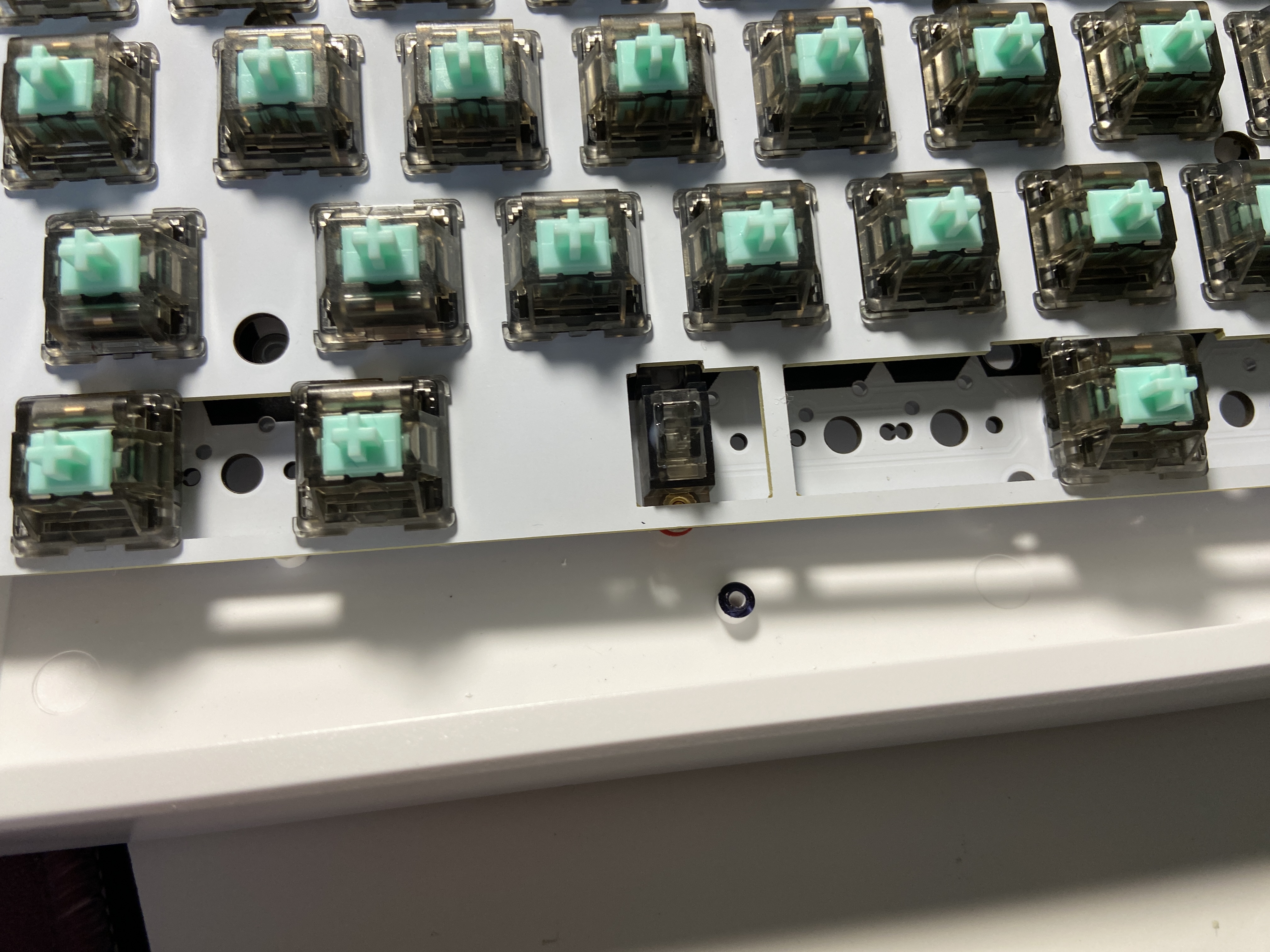
After all of these modifications are done, you can solder the switches and plate to the PCB.
The battery has a connector pre-installed from the factory, but the connector is too large to fit under the PCB in most Minivan cases.
Carefully line up the battery in the opening on the bottom of the PCB, and cut the black wire where it meets one of the outer (-) battery pads.
Strip the black wire and solder it to the (-) pad.
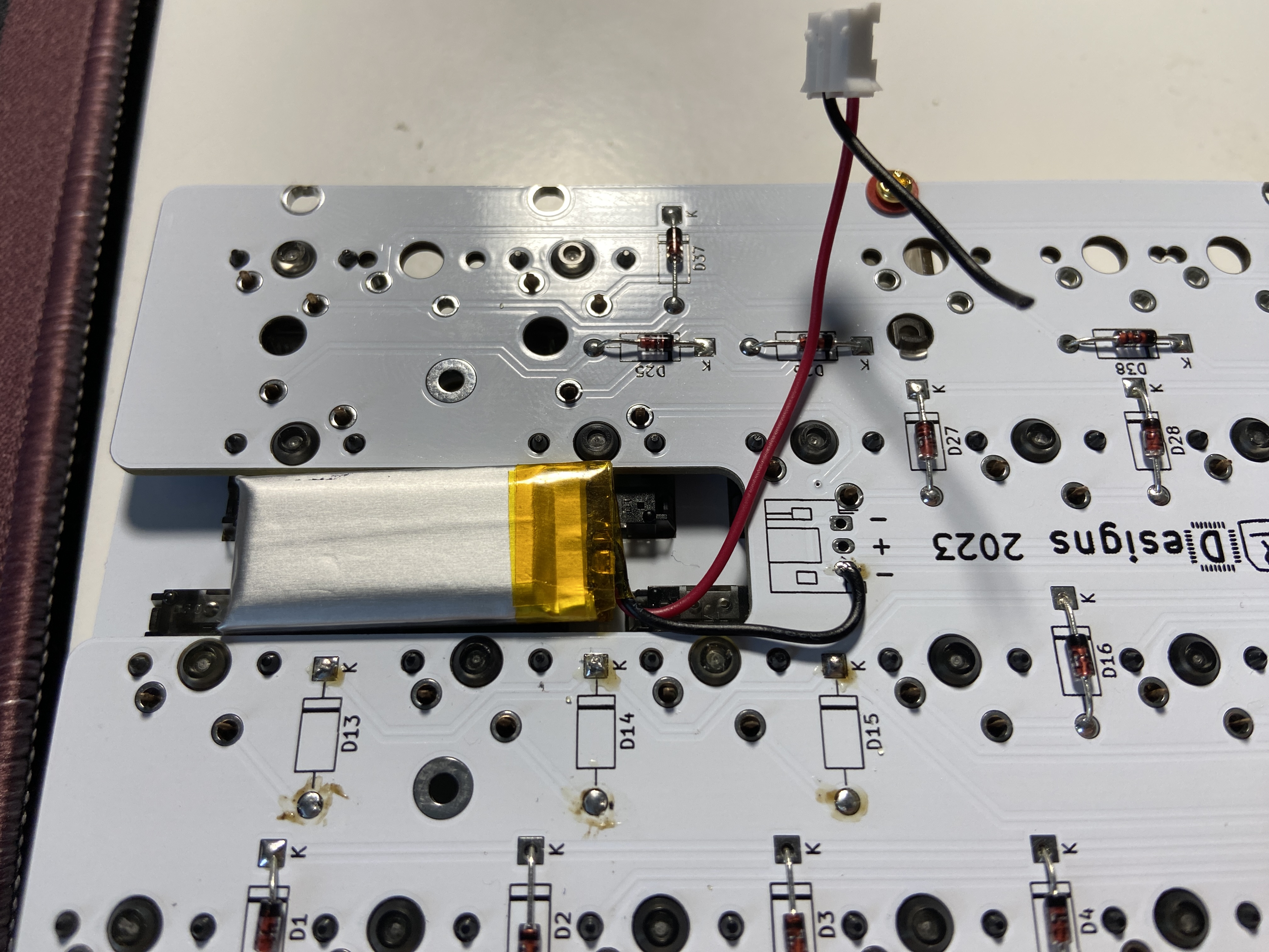
Being careful not to short the red and black wires, as this will permanently damage the battery.
Measure, cut, strip, and solder the red wire to the center (+) pad.
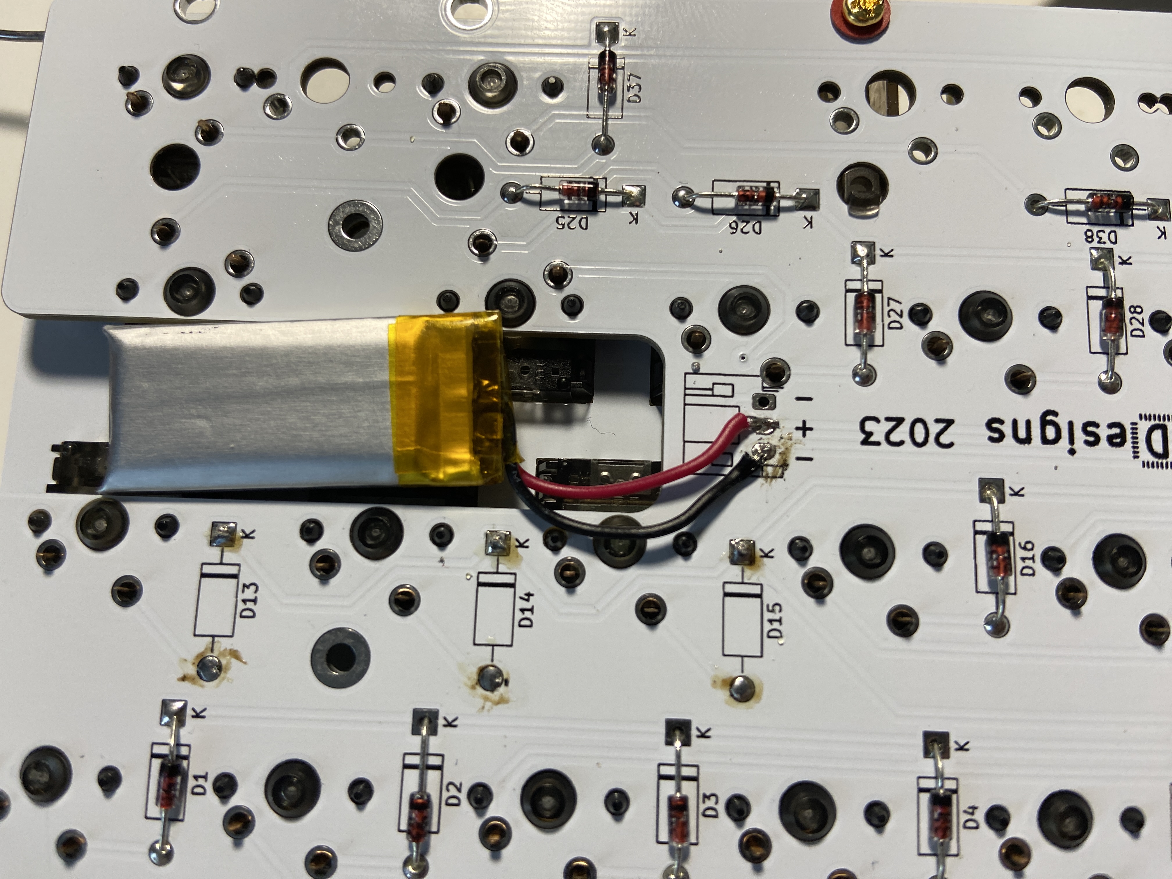
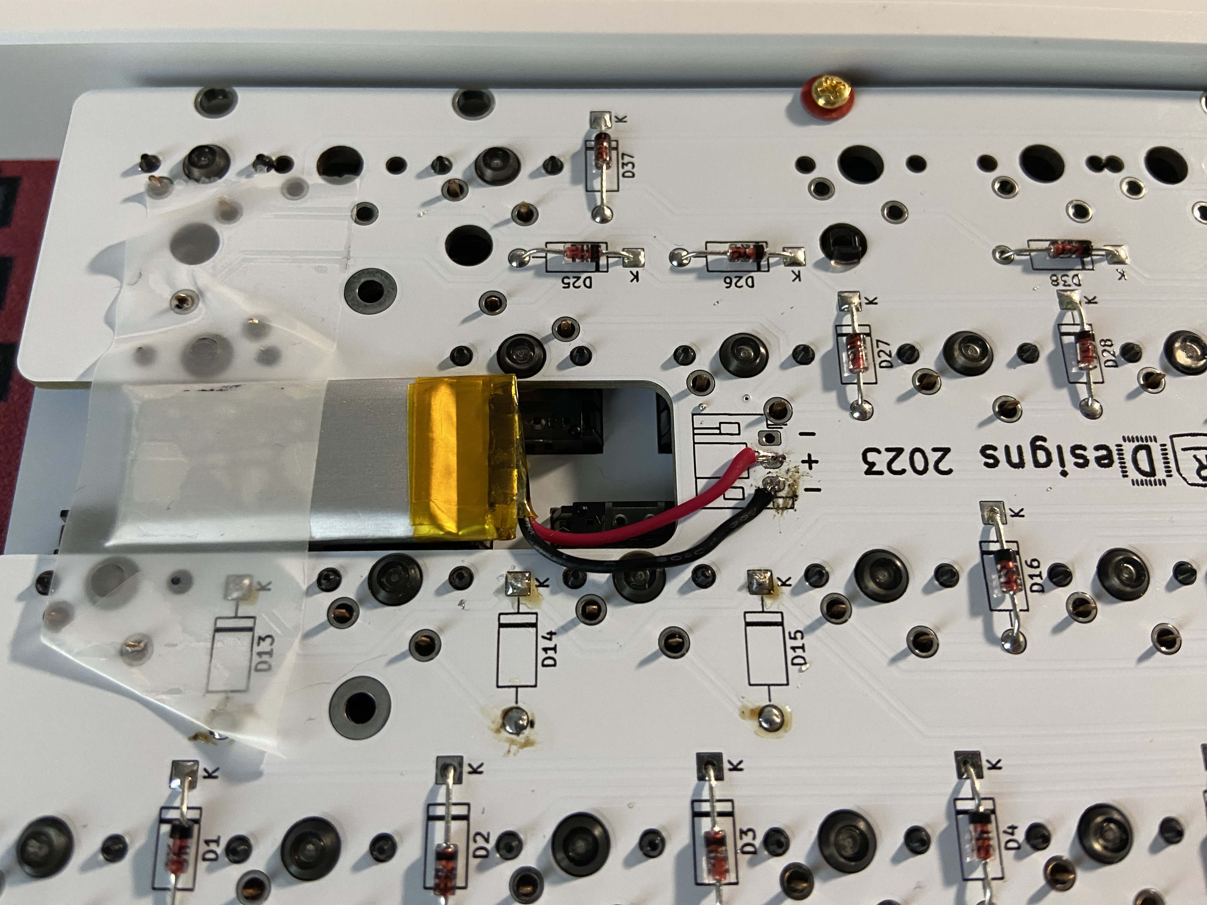
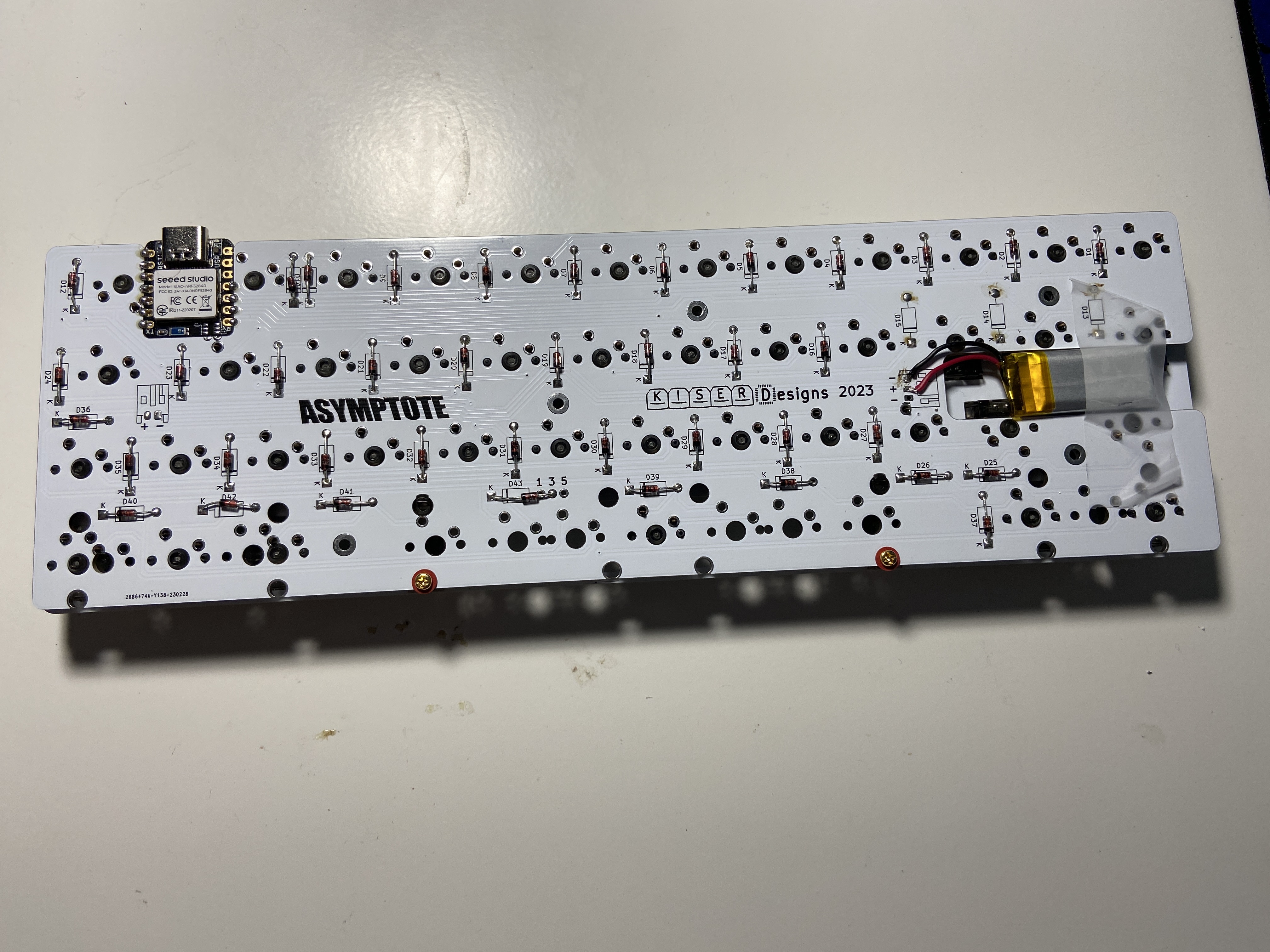
Place a bit of taper over the battery and pattery wires to prevent the battery from moving and the wires from shorting out.
Even though Scotch tape is pictured, it is recommended to use Electrical or Kapton tape.
-
Log into GitHub
-
Navigate to the Kiser Designs Asymptote ZMK Repository
-
Click
Forkin the top right:
-
Click
Create forkat the bottom: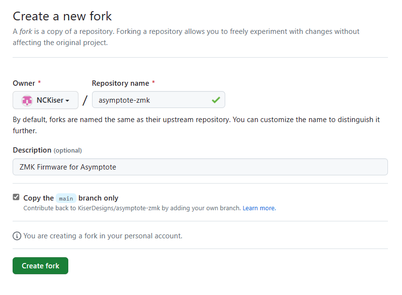
-
Once that has finished loading, navigate into the
configdirectory: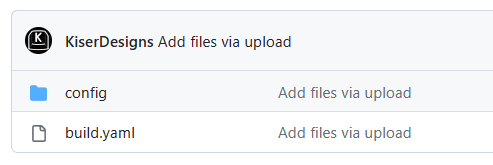
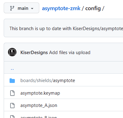
-
Find the
asymptote_[X].jsonthat matches your layout: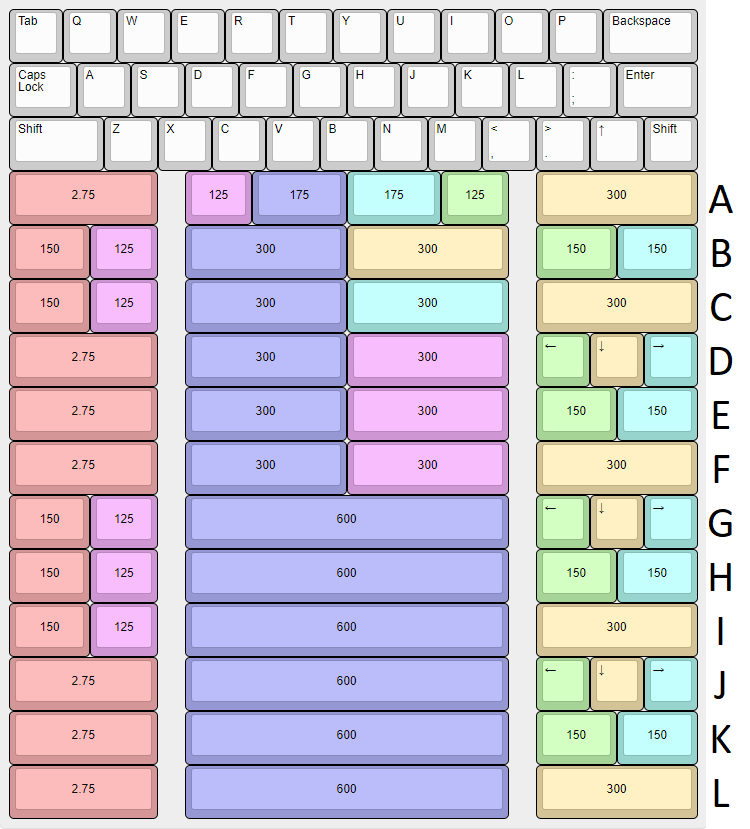
-
Edit that file, and rename it to remove the
_[X]to justasymptote.json: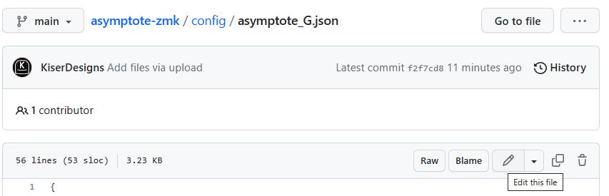
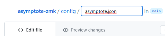
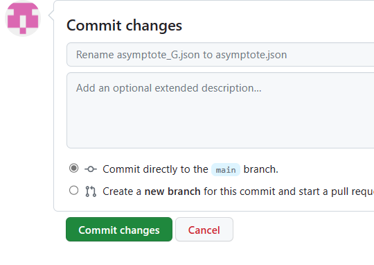
Click Commit changes at the bottom:
- Go to
Actionsin your fork ofasymptote-zmk: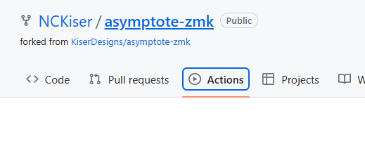
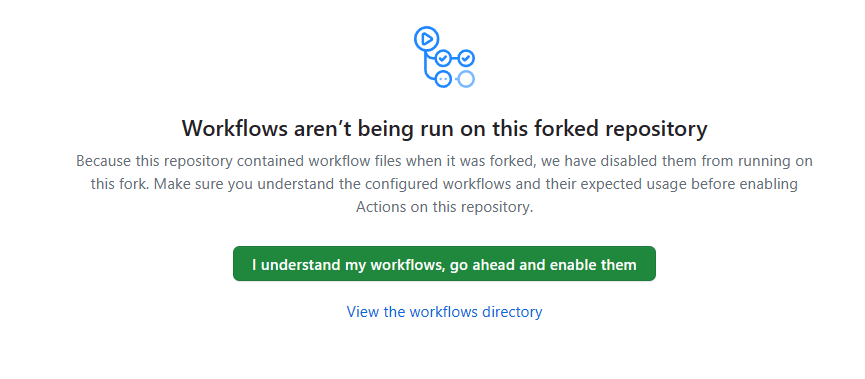
Click I understand ... enable them:
-
Naviagate to ZMK Keymap Editor
-
If prompted, click
Add Repository: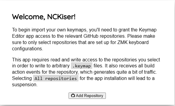
-
Select
Only select repositories, and select your fork of theasymptote-zmkrepo: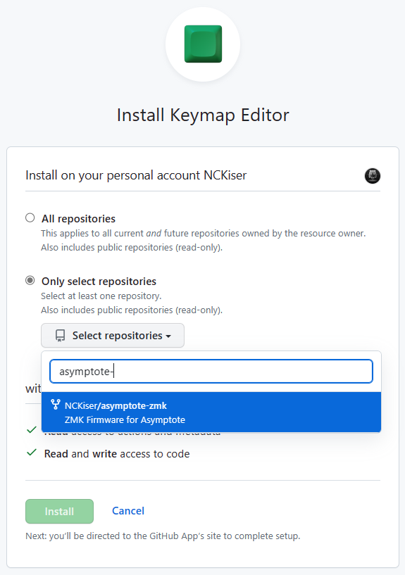
-
Click
Install, andAuthorize Keymap Editor. -
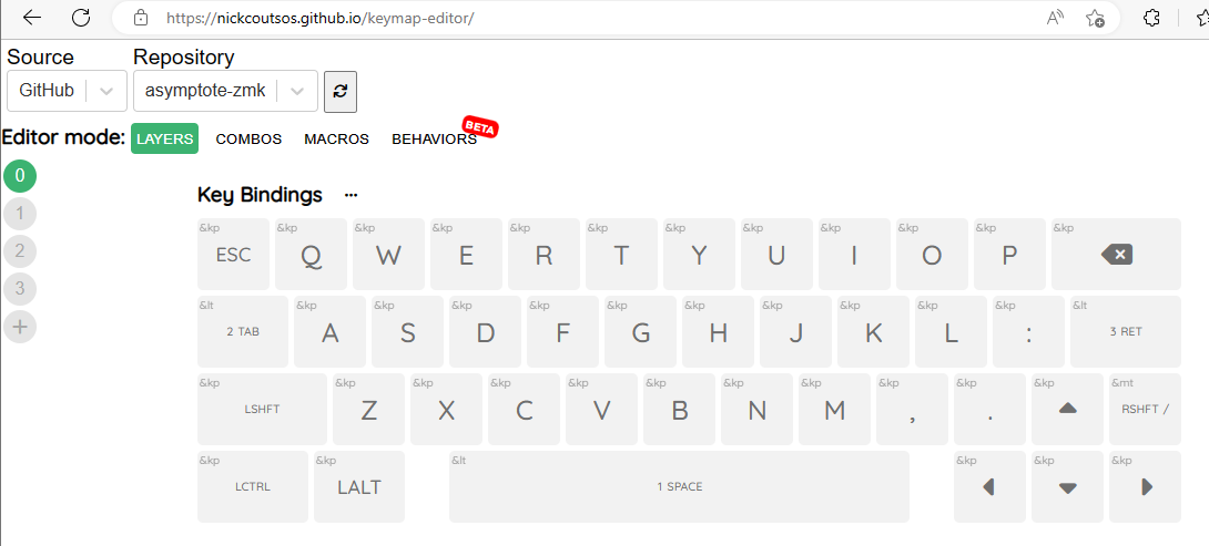
You should now be at a screen that lets you comfigure your keymap!
--- Some keys may render to the right of the keyboard. These are not mapped to any physical switch. ---
-
See the ZMK Docs for an overview different keycodes and functionality.
-
When all changes have been made, click
Commit Changesin the bottom-right: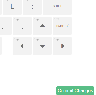
-
After a short time Refesh the Page, then click the
Firmware buildbutton in the bottom-right:
-
This may take you to an older firmware build! Click
Actionsin the top and select the most recent build (it may still be running): -
Download the firmware.zip by clicking
firmwarein theArtifactssection: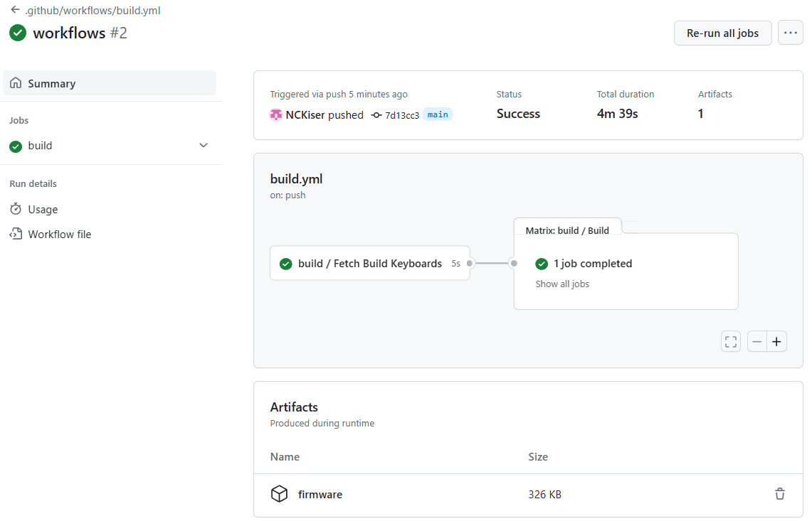
-
Plug your Asymptote into your computer and enter bootloader mode. In the default keymap, this is accessible by holding "Tab" to enter layer 2 and pressing "Esc" to enter the bootloader. If you do not have a keymap installed, double-tapping the RESET button next to the USB port on the Xiao will enter the bottoloader.
-
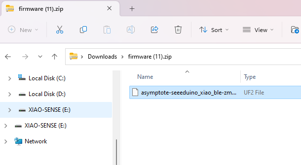
Drag-and-drop your firmware.uf2 file from the .zip you downloaded onto your board, which should show up as
XIAO-SENSE: