A Qt5-based visual editor for creating and manipulating block diagrams.
The diagram editor is designed to be controlled programmatically. This is its primary intended use case, allowing for the automatic generation of diagrams from a Python code.
To launch the editor with an empty canvas, you need to create a QApplication instance and a MainWindow.
import sys
from PyQt5.QtWidgets import QApplication
from diagrams.engine import MainWindow

if __name__ == "__main__":
    # A QApplication instance is always required
    app = QApplication(sys.argv)

    # Create the main window
    main_window = MainWindow(enable_logging=True)

    # Show the window and start the application event loop
sys.exit(main_window.start())You can use the programmatic API on the MainWindow instance to create blocks, pins, and wires. This allows you to build a complete diagram before showing the window.
The following example shows how to create a simple diagram with two blocks and diagram-level I/O.
import sys
from PyQt5.QtWidgets import QApplication
from diagrams.engine import MainWindow

def setup_example_scene(main_window: MainWindow):
    """Populates the window with a sample diagram."""
    # 1. Create blocks with pins. The create_block method returns the Block object.
    block_A = main_window.create_block("Source", input_pins=["Control"], output_pins=["Data"])
    block_B = main_window.create_block("Processor", input_pins=["DataIn"], output_pins=["DataOut"])

    # 2. Create diagram-level I/O pins.
    diag_input = main_window.create_diagram_input("System Input")
    diag_output = main_window.create_diagram_output("System Output")

    # 3. Connect the pins using the scene's create_wire method.
    if all([block_A, block_B, diag_input, diag_output]):
        main_window.scene.create_wire(diag_input, block_A.input_pins["Control"])
        main_window.scene.create_wire(block_A.output_pins["Data"], block_B.input_pins["DataIn"])
        main_window.scene.create_wire(block_B.output_pins["DataOut"], diag_output)

if __name__ == "__main__":
    app = QApplication(sys.argv)
    main_window = MainWindow(enable_logging=True)

    # Populate the scene with our example setup
    setup_example_scene(main_window)

    # Start the application
    sys.exit(main_window.start())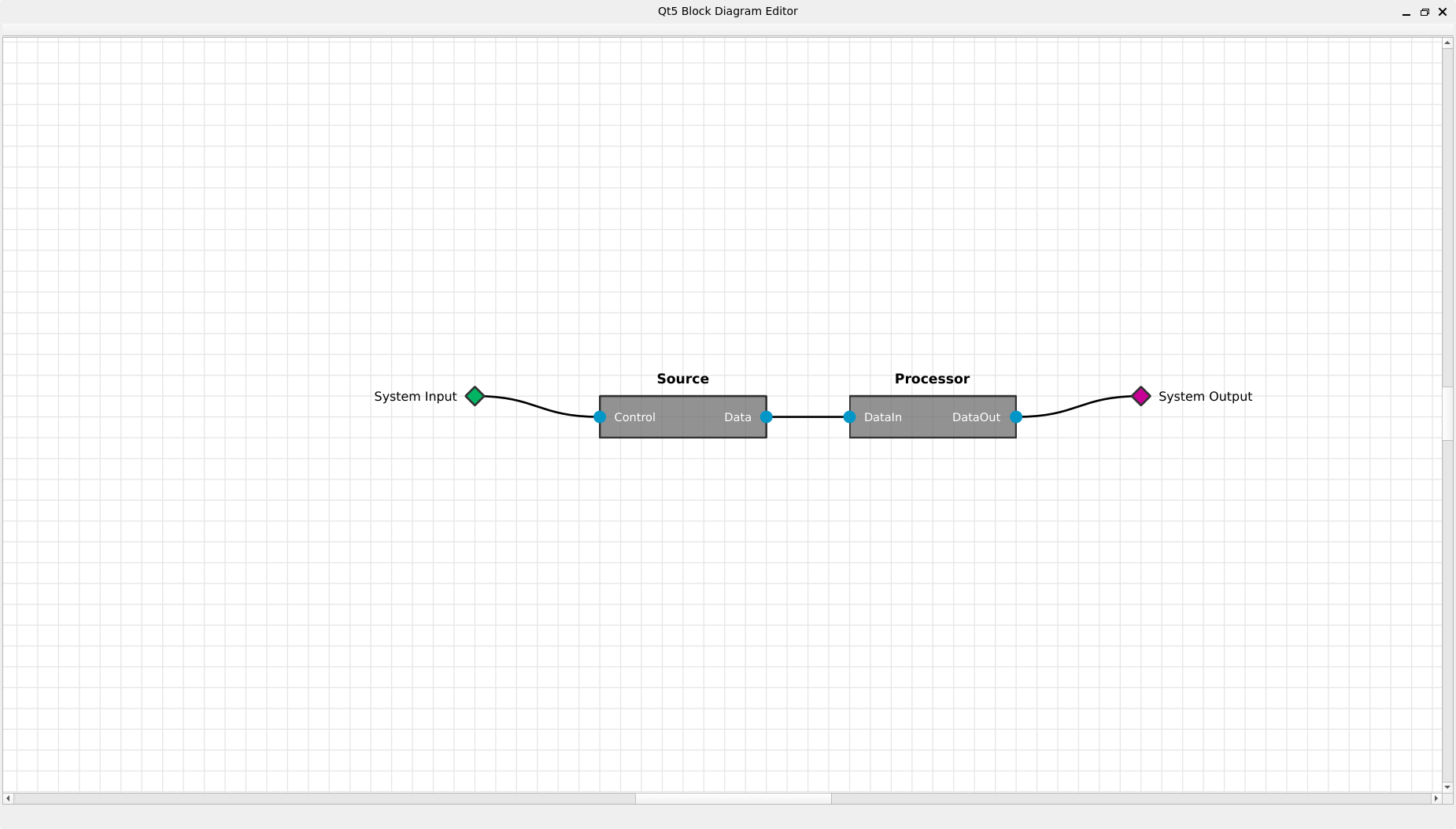
Figure 1: The outcome of the script
All interactions with the diagram are performed directly on the canvas using the mouse and keyboard.
- Pan: Click and drag with the middle mouse button to move the canvas.
- Zoom:
- Use the mouse wheel to zoom in and out. The zoom is centered on the mouse cursor.
- Alternatively, use
Ctrl++to zoom in andCtrl+-to zoom out.
- Select Item: Left-click on a block, wire, or diagram pin to select it.
- Multi-select:
- Hold Shift and left-click on items to add or remove them from the current selection.
- Click and drag on an empty area of the canvas to draw a selection box (rubber-band selection).
- Move Item: Left-click and drag a selected block or diagram pin to move it. Items will automatically snap to the grid.
- Delete Items: Select one or more items and press the
Deletekey.
- Create a Wire: Press and hold the
Ctrlkey, then left-click and drag from a source pin to a destination pin.- The connection must be from an output pin to an input pin.
- An input pin can only have one incoming wire.
- A temporary wire will follow the cursor. Release the mouse over a valid target pin to complete the connection.
Right-clicking on different parts of the canvas will bring up context-specific menus.
- Add Block: Opens a dialog to create a new block.
- Add Diagram Input: Creates a new diagram input pin.
- Add Diagram Output: Creates a new diagram output pin.
- Fit to View: Adjusts the zoom to show all items on the canvas.
- Optimize Placement: Runs the configured layout optimization algorithm to reduce wire crossings and length.
- Export to SVG: Opens a file dialog to save the current view as an SVG image.
- Unlock Everything: Unlocks all locked blocks and wires.
- Rename Block: Opens a dialog to change the block's name.
- Add Block Pin: Opens a dialog to add a new input or output pin to the block.
- Lock/Unlock Position: Toggles the locked state of the block, preventing it from being moved.
- Delete Block: Deletes the block and all connected wires.
- Lock/Unlock Wire: Toggles the locked state of the wire. A locked wire prevents its connected pins from being reordered by the optimizer.
- Delete Wire: Deletes the connection.
- Rename Diagram Input/Output: Opens a dialog to change the pin's name.
- Delete Diagram Input/Output: Deletes the pin and all connected wires.
This project is licensed under the Apache License 2.0. You are free to use, modify, and distribute this software, provided that you include proper attribution to the original author(s). Redistribution must retain the original copyright notice and this license.