Home
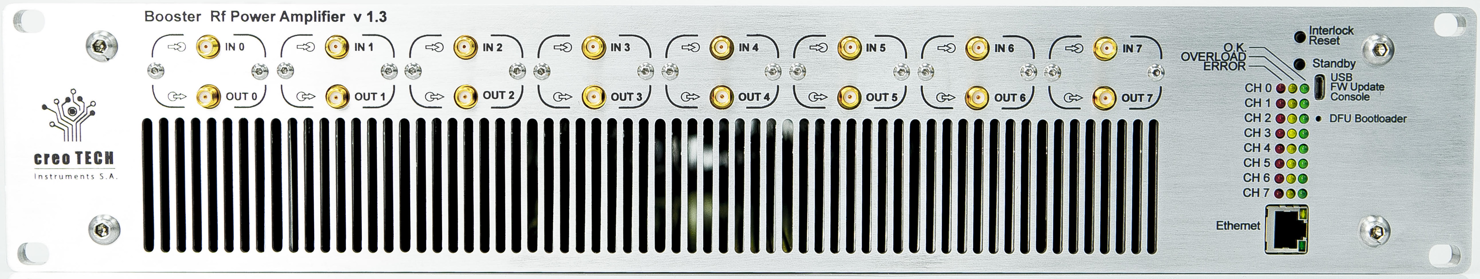
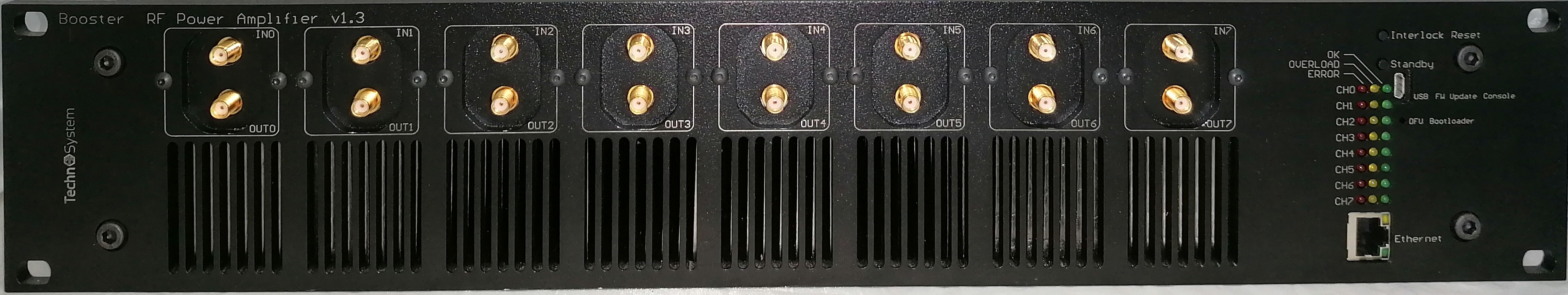
Booster is an eight channel RF power amplifier, providing several Watt of RF between 40MHz and 500MHz. Mounted in a compact 2U high 19'' chassis, it is optimised for low cost and low power consumption, while providing good RF performance. It provides full interlocking and logging via a flexible ethernet-based remote interface.
Booster is offered in two variants:
- Booster optimized for high efficiency
- Booster-HL optimized for high linearity. It offers the second harmonic at -40dBc level.
Design files (schematics, PCB layouts, BOMs) can be found at Booster/releases. The mechanical parts have their own repository at booster-mech.
The current firmware has its own repository at quartiq/booster. The legacy firmware has its own repository at booster-firmware.
Booster is currently available from TechnoSystem, Creotech, QUARTIQ, and M-Labs.

Detailed characterisation data can be found spread among various issues. (To do: sort data and post here!)
- Ethernet interface for monitoring and configuration
- User-configurable interlocks protect both Booster and sensitive loads connected to it from damage
- Per-channel remote monitoring of: input, output forward and output reverse powers; temperature; current and voltage.
- Remote shut down of individual channels via Ethernet
- Open source hardware and firmware
- Modular design with individually field-replaceable channels, for example to change the frequency band
Booster uses the following interlocks to protect itself and the loads it drives from damage:
- output forward power
- this interlock is implemented "in hardware" and has a response time of a few microseconds to prevent damage. The other interlocks are implemented in software by the microprocessor and have a typical response time of a millisecond
- user-adjustable threshold up to 39 dBm
- this interlock is primarily intended to protect sensitive loads, such as AOMs, which could be damaged by excessive RF power
- output reverse (reflected) power
- fixed 30dBm threshold
- this interlock is primarily intended to protect Booster itself from damage
- current consumption
- internal 30V and 6V supplies
- hardware fold-back protection on the 30V PA supply
- temperature
- software protection disables channel when temperature reaches 60 C
- thermal switch cuts power to entire chassis at 80 C
Yellow LEDs on the front panel indicate that an RF power interlock has tripped, red LEDs indicate an error condition, such as over temperature or communication bus error. Booster's status can also be found using the remote programming interface.
When any interlock trips, the input RF is disconnected from the amplifier using an internal RF switch. In case of an error condition, such as excessive temperature in the amplifier, the amplifier power stage is also shut down.
Once an interlock has tripped, it must be manually cleared to resume normal operation by: pressing the "interlock reset" button; the remote programming interface; or, by power-cycling Booster. Note that disabling a channel (via the remote interface or by pressing the standby button) does not reset interlocks or errors, despite the fact that the OVERLOAD and ERROR LEDs turn off as long as the channel remains in standby. Once the channel is re-enabled, the LEDs will switch on again.
Error conditions can only be cleared by power cycling Booster. The troubleshooting section has information for debugging error conditions.
The input, output forward and output reverse powers, along with diagnostics such as channel temperature and fan speed, can all be queried using the remote interface.
If the RF power is too low to be measured accurately by Booster, the reported values are clipped to the lowest accurately measurable value.
Note that, while the power measurements are a very useful feature of Booster, it is not a test and measurement grade network analyzer -- think of them as a replacement for getting out a directional coupler and power meter. In particular, high VSWRs may lead to dB-level errors in the forward power measurements.
Booster's front panel houses two push switches:
-
INTERLOCK CLEAR: resets all interlocks, equivalent to theINTERLOCK:CLEAR ALLinstruction -
STANDBY: toggles between enabling and disabling all channels, equivalent to theCHANNEL:ENABLE ALLandCHANNEL:DISABLE ALLinstructions.
By default, when Booster is turned on all channels are disabled. This behavior can be changed using the VCP interface.
To find Booster's MAC address, use the VCP macconfig command.
The minimum fan level can be configured via the VCP fanlevel command. Setting the minimum fan speed lower reduces the noise from Booster, but can lead to larger thermal fluctuations during warm-up, since the fans won't turn on until the chassis starts to heat up.
It's worth making a note of the device status, e.g. using the VCP start command when it first arrives. Watch out for any of the current draws being significantly different to the others (29V should be approx 50mA with no RF, 6V should be approx 250mA).